- 31 -
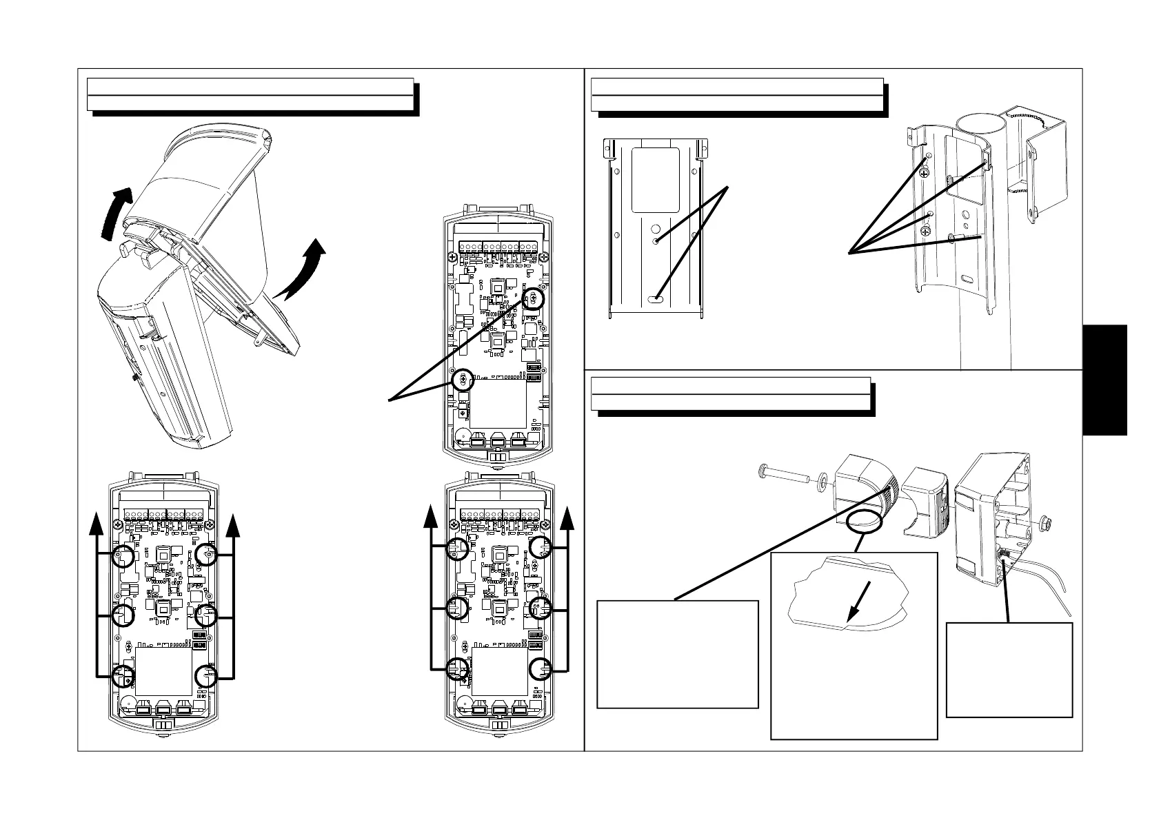
Sensor opening and board removal
1. To remove the cover,
first lift the bottom part
(1) and then unhook it
from the upper part of
the guide (2).
1
2
2. Remove the
two set screws.
3. Slide the board until the
notches A coincide with
the stops B.
4. Remove the board.
AA
BB
Wall and pole plate installation
Holes for fixing the
plate to the wall
Holes for fixing the plate
to a pole with adaptor
mod. SP-OUT
(item 1135106)
Installation of the joint
Assemble and fasten
using the Screw D and
the Nut E the various pieces
that make up the joint, as shown
in figure, before fixing
the Wall side bracket A
to the wall.
A
B
C
F
E
D
ATTENTION
Before fixing the
wall joint, install the
anti-tampering
module
ATTENTION
Position the Sensor side
joint C verifying that the
45° notch is on the
bottom and the 90° one
is on the top
For passing connection
cables and those of the
anti-tampering module,
use the existing space
above the Screw D
E
N
G