- 16 -
IST0570V3.1
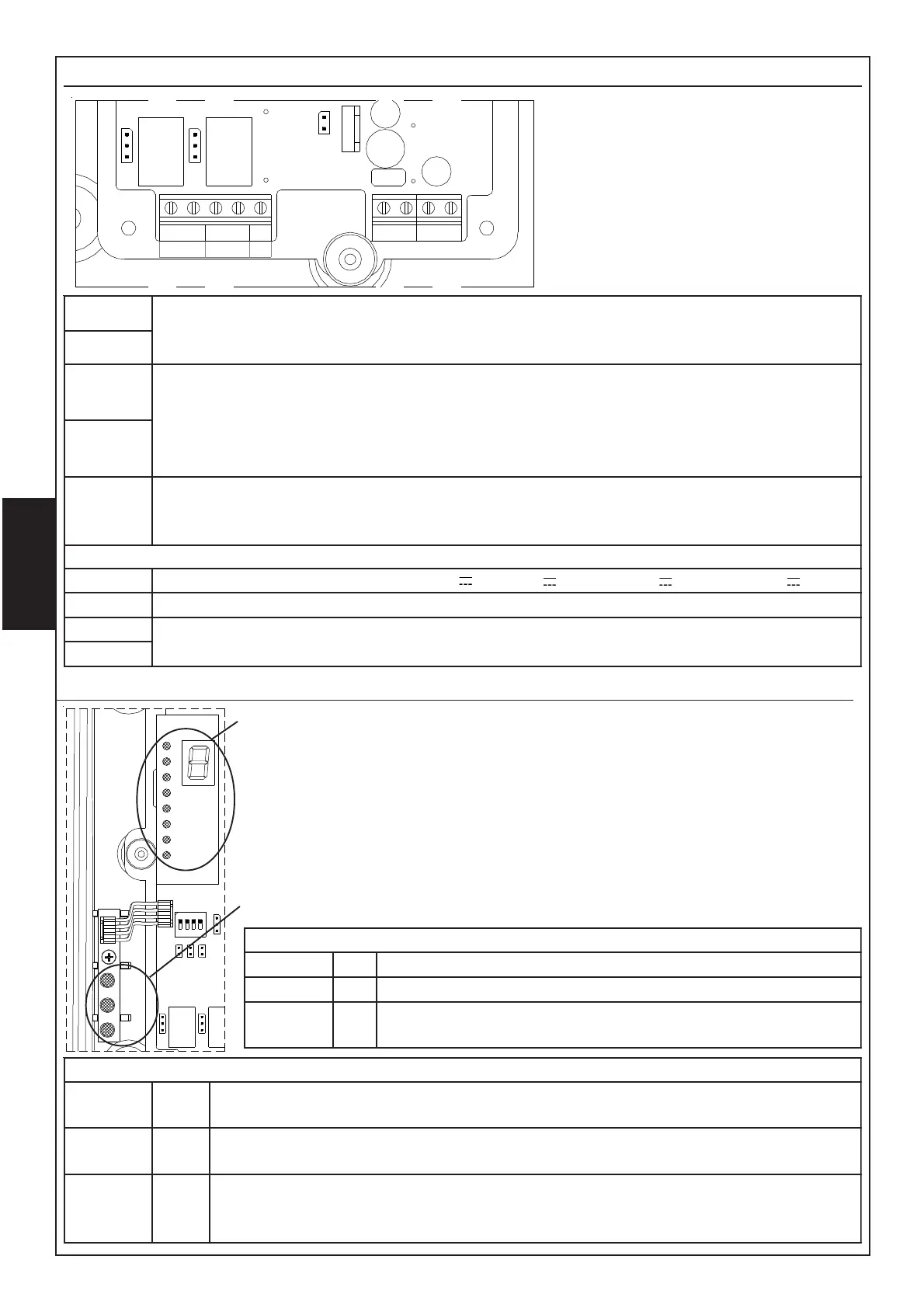
Terminal Board
A
-
BC
GUASTOALLARME
S7
NC
C
NO
NC
NO
S8
OUT
+F
+
S6
The terminal board is made of
two separate groups: the one
on the left concerns alarm and
fault-condition output whilst the
one on the right concerns
supplying input and serial door.
ON/CN
MRALA
.yalerMRALAfoegnahcxE
.detcetedneebsahekomsretfasdnoces04tuobaevitcasitI
.ON/CroCN/Cegnahcxeehttesotredroni7SrepmujnotcA
ON/CN
TLUAF
NOITIDNOC
.yalerTLUAFfoegnahcxE
langisehtfopordneddusfonoitcetedretfaetunimenotuobaevitcasitI
ehtetasnepmoctonseodnoitarbilac-flesnehwrolevelmuminimrednu
.pordlangis
.ON/CroCN/Cegnahcxeehttesot8SrepmujnotcA
C
F+TUO
fonoitcennoctceridehtswollatuptuosihT.yalermralaehtsasetavitcatI
ehtmralagniruD.tinulortnoceriflanoitnevnocfoenilenootmaebeht
.mho086siegrahcecnetsiser
+ )V8,72xam/V5,11.nim(V42roV21evitisopgniylppuS
- evitagengniylppuS
A
001RBeludomlanoitpootnoitcennocrofroodlaireS
B
Signalling Led
Module to visualize the signal:
– during normal working, display visualizes the signal value whilst Leds bar
visualizes the percentage of masking.
– during alarm condition the letter A is visualized.
– during fault condition the letter F is visualized.
- during calibration the display visualizes the unit values whilst the Leds bar
visualizes the decimal values of signal received.
Module for visualization of detector condition:
EDOMNOITARBILAC
DER
2DL
FFO
NEERG
3DL
NO
WOLLEY
4DL
FFO
gnihsalF
noitarbilaccitamotuA
)NOni3piD(noitarbilaclaunaM
EDOMLAMRON
DER
2DL
FFO
NO
noitidnoclamroN
mralA
NEERG
3DL
gnihsalfwolS
gnihsalfkciuQ
)sdnoces2yreve(noitidnoclamroN
dlohserhtmralaehtgnideecxeekomshtiW
WOLLEY
4DL
FFO
gnihsalfkciuQ
NO
noitidnoclamroN
mrala-erpnoitidnoctluaf(muminimrednulevellangiS )
noitavitcayalertluaffoemitemasehttA
LD3
LD4
2
3
4
5
6
7
8
LD2
1