- 23 -
IST0570V3.1
ALLARME
NO
NC
+FGUASTO
C
NO
NC
C
OUT
+
- BA
R1
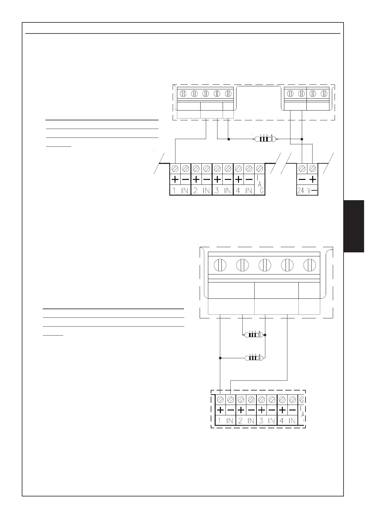
Connections to Control Units
BF100R beam is equipped with:
ALLARME
NO
NC
+F
GUASTO
C
NO
NC
C
OUT
R1
R2
In both cases, if module BR100 is used, reset can be done through mechanical key on board.
- Relay ALARM output.
Contacts of this output can be C/NC or C/NO
according to setting of jumper S7 (see chapter
JUMPER).
In order to reset the beam from alarm
condition, it is necessary to take off supplying
from the beam for a few seconds (Jumper S9
open).
An example of connection using these contacts is
shown on side-drawing where ALARM contact is set
on C/NO and FAULT relay is set on C/NC.
R1 is the end-line resistence which is usually given
within control unit.
R2 is the alarm resistence (for AVS control units
the value of this resistence is 680/1000 ohm –
3W) (not included).
- OUT + F for direct connection to AVS
conventional fire control units (charge
of 680 ohm during alarm).
In order to reset the beam from alarm
condition, simply make a reset
operation on control unit (Jumper S9
closed).
Side-drawing shows an example
of connection using these
contacts: R1 is the end-line
resistance usually given with
control unit. FAULT contact is set on
C/NC.