- 22 -
IST0570V3.1
LD3
LD4
LD2
4321
ON
S1
S8
+F
OUT
NO
ALLARME
NO
GUASTO
C
NC
C
NC
S4S 3
S6
S2
S7
+
- BA
S5
LD3
LD4
LD2
4321
ON
S1
S8
+F
OUT
NO
ALLARM E
NO
GUASTO
C
NC
C
NC
S4S 3
S6
S2
S7
+
- BA
S5
LD3
LD4
LD2
4321
ON
S1
S8
+F
OUT
NO
ALLARME
NO
GUASTO
C
NC
C
NC
S4S 3
S6
S2
S7
+
- BA
S5
LD3
LD4
LD2
4321
ON
S1
S8
+F
OUT
NO
ALLARM E
NO
GUASTO
C
NC
C
NC
S4S 3
S6
S2
S7
+
- BA
S5
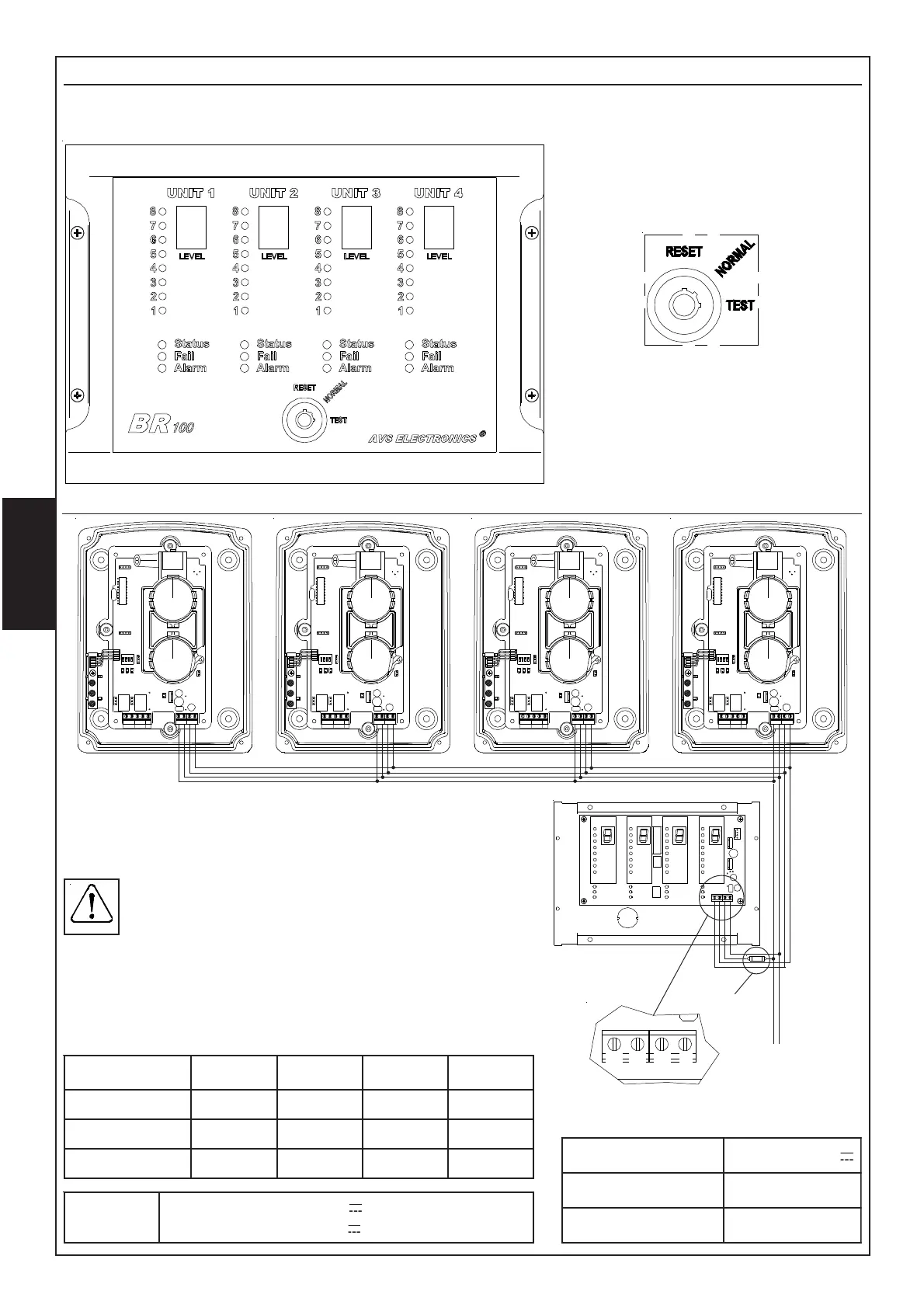
BR100
In order to obtain signal visualizatioin in real time, it is possible to remote the display/led module of
any single beam, locating it in remote panel BR100.
Any BR100 remote panel can locate
up to 4 display/Led modules.
Dialogue between the remote panel and the beam occurs
thanks to a serial connection as shown on side drawing.
Connect A and B terminals of beam to concerned A and B
terminals on BR100 remote panel.
BR100 supplying must be separate from beams
supplying as a possible short-circuit in remote panel
supplying may cause a cut in beams supplying
(EN54-12 norm). To this purpose use 500 mA fuse
together with its fuse-holder given within BR100 panel.
Single beams connected to BR100 must be addressed using
Jumpers S2, S3 and S4 on board (see chapter JUMPER), in
the following way:
+
-
REIRRAB 1 2 3 4
2S
DESOLC NEPO NEPO NEPO
3S
NEPO DESOLC NEPO NEPO
4S
NEPO NEPO DESOLC NEPO
Supplying
Fuse
A
B +
-
noisnetlanimoN V8,72-5,11
noitpmusnoC Am011xam
esuF V052LA5.0F
TECHNICAL FEATURES
RESET: it makes a reset of alarm
condition.
NORMAL: during normal working of
beams.
TEST: it triggers off a total alarm of
all connected beams.
BR100 Connection
1S
:nepO
:desolC
gniylppusV42
gniylppusV21