Other display indications
As stated before, at power up an initialization procedure of about 1 minute takes place, during
which the equipment configures itself according to programming parameters stored in the SIM
card. The 7-segments display shows some default characters to indicate the advancement of
this process:
at the beginning, a line shifts on the display from bottom to top. Then an A character flashes
for about 30 - 40 seconds. Finally, a C character shows till the end of the initialization, when the
led bar will start to indicate the signal strength.
Additional messages on the display:
: An horizontal line shifting from bottom to top is displayed when sending an SMS message.
C : The C character is displayed when executing the periodic autotest with SMS sending.
F (flashing) : This character indicates PSTN line fault condition.
8 (blinking) : Indicates an incoming call through the GSM.
Trouble and Fault messages:
0 = VECTOR Plus is not able to turn on the GSM unit.
1 = Wrong or missing serial comunication between VECTOR Plus and GSM unit.
2 = Wrong PIN security code on the SIM card.
(correct value 0000)
3 = No GSM service available
4 = Poor signal level
5 = Battery problem (only when using standard cell phone)
6 = Unknown general problem
Testing VECTOR Plus
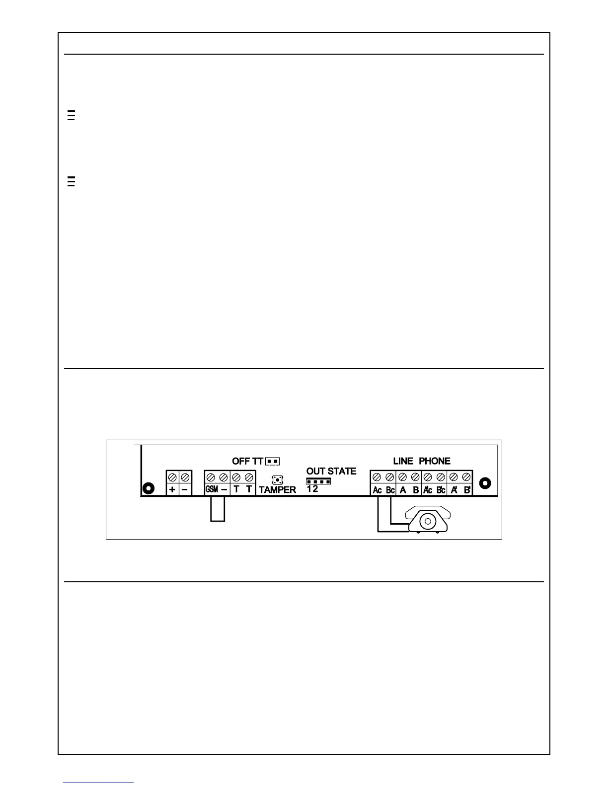
In order to verify the efficiency and the signal quality of the GSM channel, we suggest the
following test: connect a normal telephone set to terminals Ac - Bc of the interface and close to
negative the terminal "GSM". Power up the unit and wait the initialization process is completed
(see display). Execute some telephone calls and evaluate the signal and audio quality of the GSM
connection.
Jumpers and trimmers
Jumper S1: closed if using Siemens cell phones - open if using industrial GSM engine
Jumper S2: open if using Siemens cell phones - closed if using industrial GSM engine
Jumper S3: (OFF - TT) closed disables the tamper switch
RV5: serves to adjust the GSM unit voltage - 3,85V for industrial GSM engine - 8,5V for
Siemens cel phones. (WARNING: Avoid mounting the industrial GSM engine if voltage is adjusted for
Siemens cell phones, because it will cause permanent damage of the GSM module)
RV2: adjusts the audio level of the signal received from the GSM unit.
RV3: adjusts the audio level of the signal applied to the GSM unit for transmission.
(NOTE: RV2 and RV3 are factory adjusted to recommended values. Therefore additional adjustment
normally is not needed)
PB1: Tamper switch connected to the TT terminals.
PB2: Microprocessor reset switch.
5