Sigma IHT Version 4 Quickstart Testing
QUICKSTART 2 - 2 ©2003 N J Froment & Co Ltd
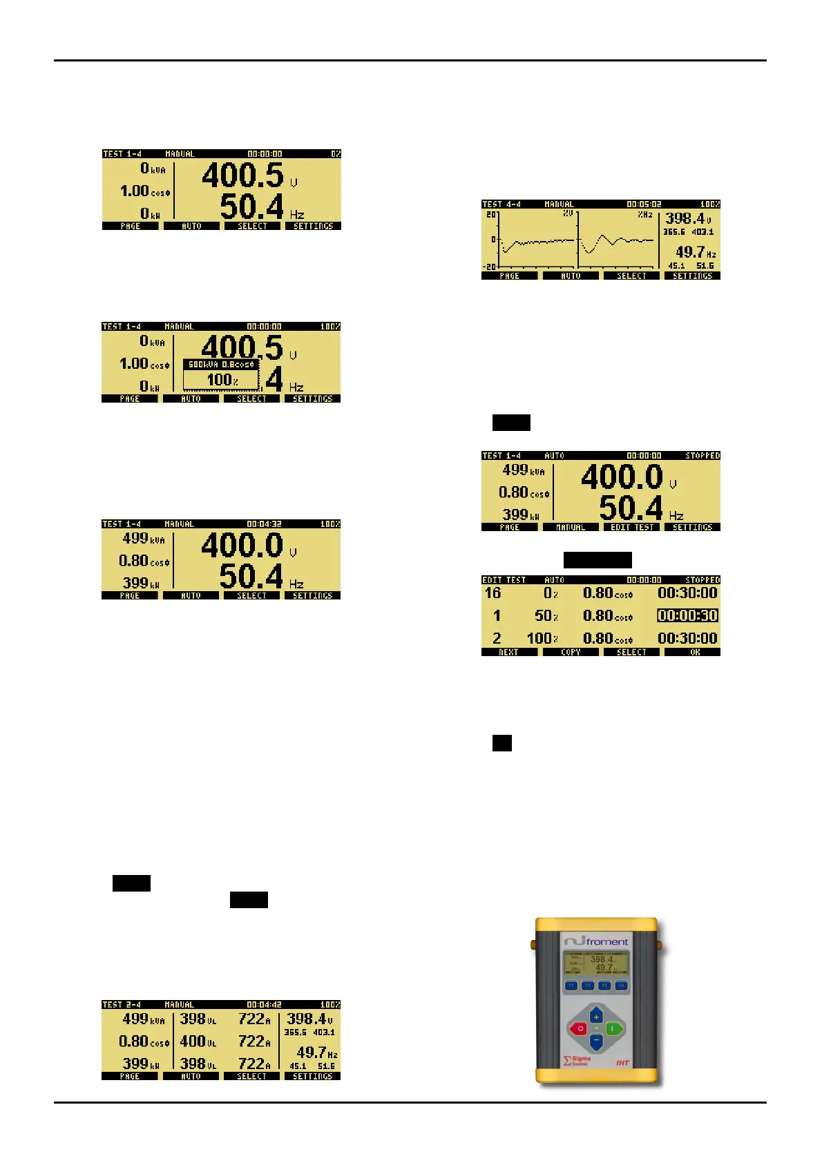
5. Apply Load
There are four TEST pages; which offer different views of
the instrumentation. When you select
TEST for the first
time the following page is displayed.
You can select and apply load on any of the four
TEST
pages in the same way.
• Select the required load using the
+ and
-
keys. By
default load control is in percentages. The screen will
change to show the load selected pop-up.
Pressing the SELECT key changes between load control in %, kW or kVA
and power factor. If a resistive-only load bank is used, then the selection will
be % and kW only.
• Apply the load by pressing the green l key. The load
selected pop-up will disappear and the green LED on
the IHT will light up.
The selected load pop-up will disappear after 3 seconds or when another key
is pressed, but selected load is always displayed on the right of the status
line.
Each time you press I, load correction will ensure you get the exact load
requested. Load correction can be enabled and disabled from OPTIONS.
• Load can be removed at any time by pressing the red
O key.
The first TEST instrumentation page shows the real-time Voltage and Frequency in
large fonts, together with the power in kVA, cos Φ and kW. Along the top, the
Status line shows that we are in MANUAL, and 4 minutes and 32 seconds has
elapsed since the last load accept. The selected load is displayed on the top right
of the status line.
Use this page when initially adjusting the AVR and governor settings.
6. View the Instrumentation
• Press PAGE to change to the next instrumentation
page. After four presses of PAGE you will be back to
page one.
The next two TEST pages shows all the true rms three-
phase measurements of Voltage (V), Frequency (Hz),
Current (A), Power (both kW and kVA) and Power Factor
(Cos
Ø).
The second and third instrumentation pages provide all the electrical data required
when full-load testing. Displayed on the right are the voltage and frequency; below
each are the maximum and minimum values for the last load change.
Note that page two shows line-line voltages, whereas page three shows line-
neutral voltages
The fourth TEST page provides a graphical view of the
voltage and frequency when the last load was applied.
The voltage and frequency graphs display the first 6 seconds of the last load
change, as a percentage of the supply voltage and frequency rating.
Use this page when testing governor and AVR transient response.
7. Using Automatic Load Control
At any time you can change between manual and automatic
load control.
• Press AUTO for automatic load control. Press F2
again to return to
MANUAL.
• A pre-programmed sequence of up to 16 loads can set
up by pressing the EDIT TEST key.
Again, use the + and – keys to change the selected value. Press SELECT
to select either %, cos Φ or time.
Pressing NEXT moves down to the next line. You can press COPY to copy
the selected value down to the next line.
• Press OK to exit EDIT TEST.
• Pressing the green
l key will start the sequence.
• Load can be removed, and the automatic sequence
stopped, by pressing the red
O key.
The status of the automatic test is shown on the right of the status line.
Any sequence that is running will be paused if MANUAL, EDIT TEST or
SETTINGS are pressed. Pressing I will restart a paused load sequence.
Whilst the test is running the + and - keys can be used to quickly override the
selected load. Press I to apply the new load selected.
 Loading...