30.3 WOLF DEVICE ANALOG AND MPX BREAK-OUT BOX (WLF-BBAM)
11
11
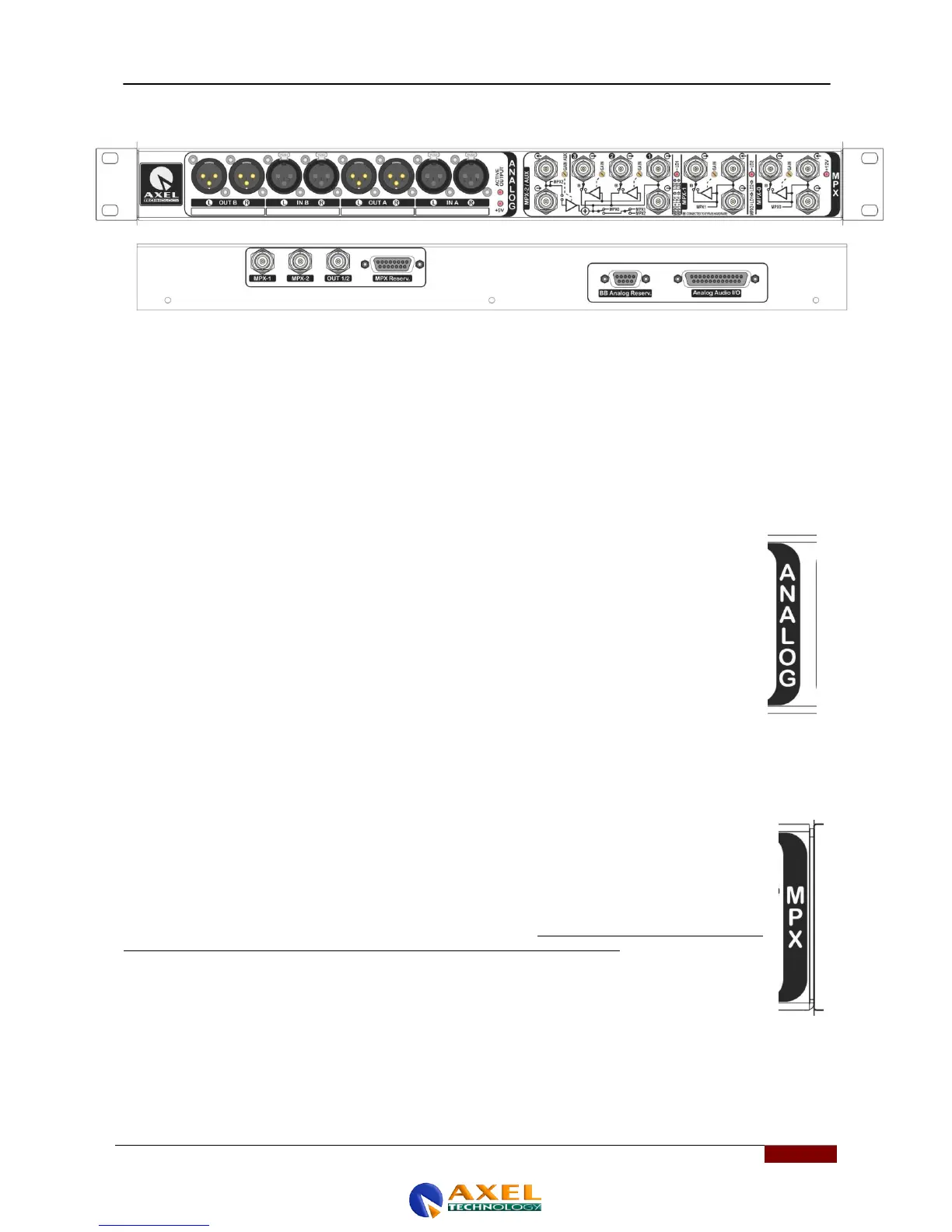
The analog Breakout Box is divided into two sections:
The ANALOG section (12 right-hand MPX section BNC connectors)
MPX section (made up of the 8 left-hand male XLR connectors)
30.4 ANALOG SECTION
The ANALOG section features:
- transformer-coupled input A
- transformer-coupled input B
Electronically balanced output (OUT1 - A)
- electronically balanced replica (OUT1 - B) of output OUT1-A
A relay-based hardware bypass system (see Relay1, Relay2, and Relay3 and Relay4 in figure) is used to
establish direct physical contact between inputs and outputs in the event of a power failure. This is done to
prevent interruptions in the transmission chain in the event of a power failure. In particular, the bypasses
performed in the event of power failure are as follows:
- RH output OUT1 A – with RH input IN A
- LH output OUT1 A – with LH input IN A
- RH output OUT1 B – with RH input IN B
- LH output OUT1 B – with LH input IN B
The MPX section features:
The MPX Breakout Box with 12 BNC connectors. it is connected to the WOLF device via two inputs, MPX-1 and MPX-2
on the central unit and via a dedicated cable for the BB MPX connector. As the block diagram below shows, the
Breakout Box features the same two inputs, MPX-1 and MPX-2, already featured on the rear panel of the Wolf, with the
addition of a foldback output for each of them (i.e. a replica signal of the input signal buffered independently). In addition,
the Breakout Box features an MPX output associated, via internal relay, to the MPX-1 input or the MPX-2 output, in
conjunction with any AUX signal that might be present.
11
In the event of power failure, a relay establishes a direct connection (via hardware bypass) between the AUX
input and the aforesaid output. Finally, the Breakout Box has two equivalent test outputs, which repeat the
signal available at the Out MPX output.
Each of the two input sections (the sections dedicated to connection to the signal to be distributed) provides
locally, in turn, a buffered output with adjustable level via trimmer and a second non-buffered (passive) output,
which is useful for direct monitoring of the signal injected at the input. N.B: the application of a load signal to
this output can have direct effects on the signal present at the input connector. The buffered output is
equipped with a relay hardware bypass circuit that connects 'mechanically' to the input connector in the event
of a power failure.