Appendix D: The Auxiliary IO Port AXIS 200+ Users Manual
86
By connecting a digital microcircuit to a particular door for example,
it is possible to take a snapshot on each occasion that it opens or
closes.
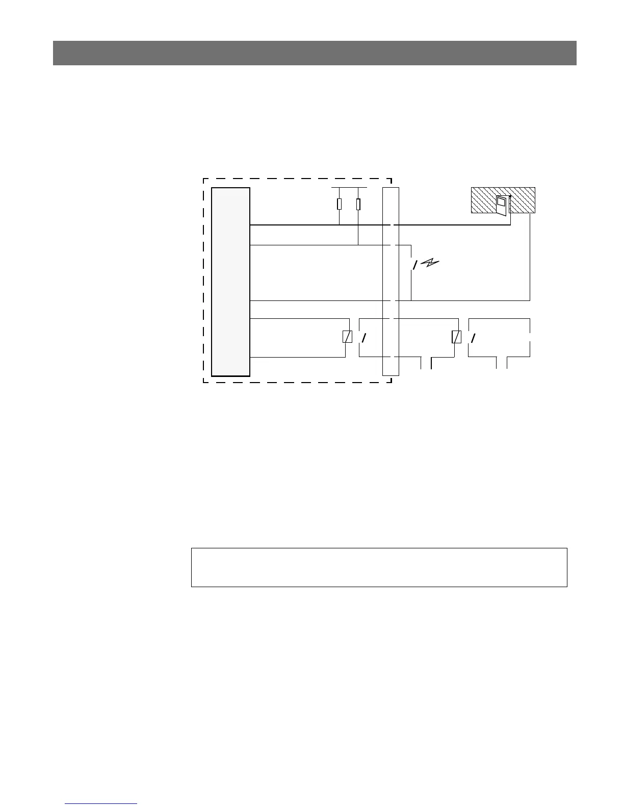
Schematic diagram of the AXIS 200+ auxiliary connector
- displaying a possible application
Status information for each of the two digital inputs is presented
within a text string. The status of the inputs can be read by clicking
on the
input.txt parameter in the above URL. The string will
amongst other things define the time and duration of the last trigger
event for the each input:
input:1 current:0 last:1 pulse:2 time_of_change:12.22
input:2 current:1 last:0 pulse:6 time_of_change:14.46
o
o
CPU
.
o
x
6
8
o
o
Digital input 1
GND
Relay
Switch
5V
Mains Power
o
o
o
o
o o
24V DC
o
o
7
o
Digital input 2
.
.
Micro-switched door
.
Infra-red switch
AXIS 200+
Aux.
Con.
Appliance
o o
Relay +
Relay -
Optional
Relay
Switch
1
2