3
5
6
8
7
4
5
6
9
1. UNIT
2. RELEASE CAGE
3. DASH
4. HEX NUT
5. LOCK WASHER
6. PLAIN WASHER
7. CAR BODY
8. REAR SUPPORT STRAP
9. TAPPING SCREW
10. M5 X 15 HEX BOLT
TO SUPPORT THE UNIT
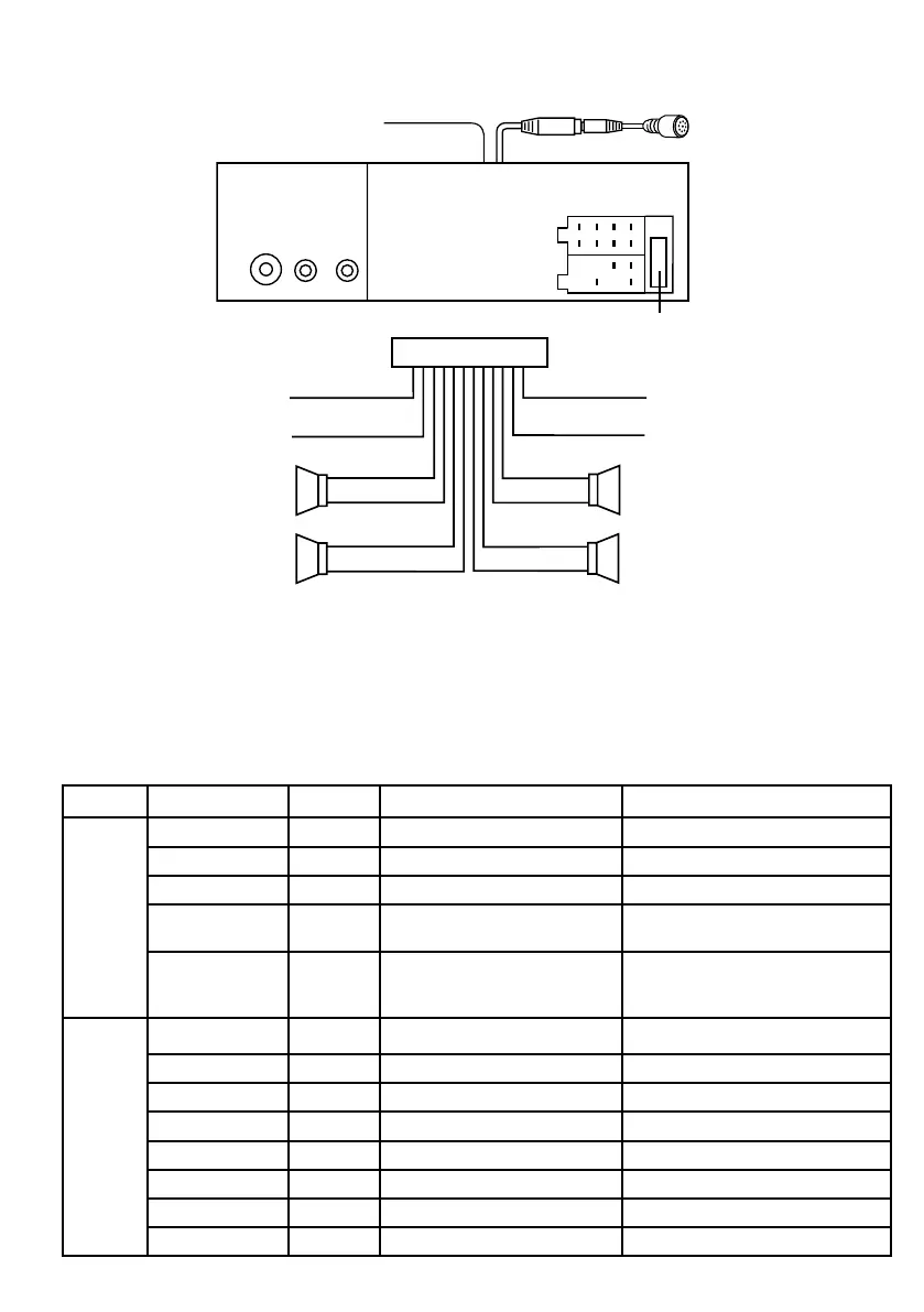
WIRE CONNECTION
Maintenance
FUSE REPLACEMENT
If a fuse blows, check all power connections and replace the fuse. If the fuse blows check for an
electronic or wiring fault. In this case, consult your nearest service centre.
Warning
Use the specied amperage fuse for each lead. Use of a higher amperage fuse may cause serious
damage and void the warranty.
Dashboard
GREY +
GREY/BLACK –
FRONT
RIGHT
SPEAKER
VIOLET +
VIOLET/BLACK –
REAR
RIGHT
SPEAKER
FRONT
LEFT
SPEAKER
REAR
LEFT
SPEAKER
+ WHITE
– WHITE/BLACK
+ GREEN
– GREEN/BLACK
ISO A/B PLUG
POWER
ANTENNA
BLUE
IGNITION SWITCH (B+)
RED
MEMORY
YELLOW
BACK UP
BLACK
GROUND (–)
LINE OUT
L (WHITE) R (RED)
ANTENNA
CONNECTOR
ISO CONNECTOR
B
A
FUSE 5A
CONNECT TO EXTERNAL MICROPHONE
TELEMUTE
1
2
3
4
4
5
5
6
7
7
8
8
5
6
8
7
4
5
6
9
1. UNIT
2. RELEASE CAGE
3. DASH
4. HEX NUT
5. LOCK WASHER
6. PLAIN WASHER
7. CAR BODY
8. REAR SUPPORT STRAP
9. TAPPING SCREW
10. M5 X 15 HEX BOLT
TO SUPPORT THE UNIT
WIRE CONNECTION
Maintenance
FUSE REPLACEMENT
If a fuse blows, check all power connections and replace the fuse. If the fuse blows check for an
electronic or wiring fault. In this case, consult your nearest service centre.
Warning
Use the specied amperage fuse for each lead. Use of a higher amperage fuse may cause serious
damage and void the warranty.
GREY +
GREY/BLACK –
FRONT
RIGHT
SPEAKER
VIOLET +
VIOLET/BLACK –
REAR
RIGHT
SPEAKER
FRONT
LEFT
SPEAKER
REAR
LEFT
SPEAKER
+ WHITE
– WHITE/BLACK
+ GREEN
– GREEN/BLACK
ISO A/B PLUG
POWER
ANTENNA
BLUE
IGNITION SWITCH (B+)
RED
MEMORY
YELLOW
BACK UP
BLACK
GROUND (–)
LINE OUT
L (WHITE) R (RED)
ANTENNA
CONNECTOR
ISO CONNECTOR
B
A
FUSE 5A
CONNECT TO EXTERNAL MICROPHONE
Block Wire Colour Pin-Out Function Connection
A
Yel l ow 4 Positive power supply Battery Positive pole
Black 8 Negative power supply Battery Negative pole or vehicle chassis
Red 7 Automatic power on/o with key Accessories or ignition supply
Blue 5
12V output for either an amplied
antenna or amplier trigger
Antenna 12V input or amplier REM
input (OPTIONAL)
Brown
Tele-mute – When this wire is
grounded by the factory Bluetooth
system, the radio is muted
Factory Bluetooth negative mute output
(OPTIONAL)
B
White 5 Front le positive speaker output Front le speaker positive input
White/Black 6 Front le negative speaker output Front le speaker negative input
Grey 3 Front right positive speaker output Front right speaker positive input
Grey/Black 4 Front right negative speaker output Front right speaker negative input
Green 7 Rear le positive speaker output Rear le speaker positive input
Green/Black 8 Rear le negative speaker output Rear le speaker negative input
Purple 1 Rear right positive speaker output Rear right speaker positive input
Purple/Black 2 Rear right negative speaker output Rear right speaker negative input
 Loading...