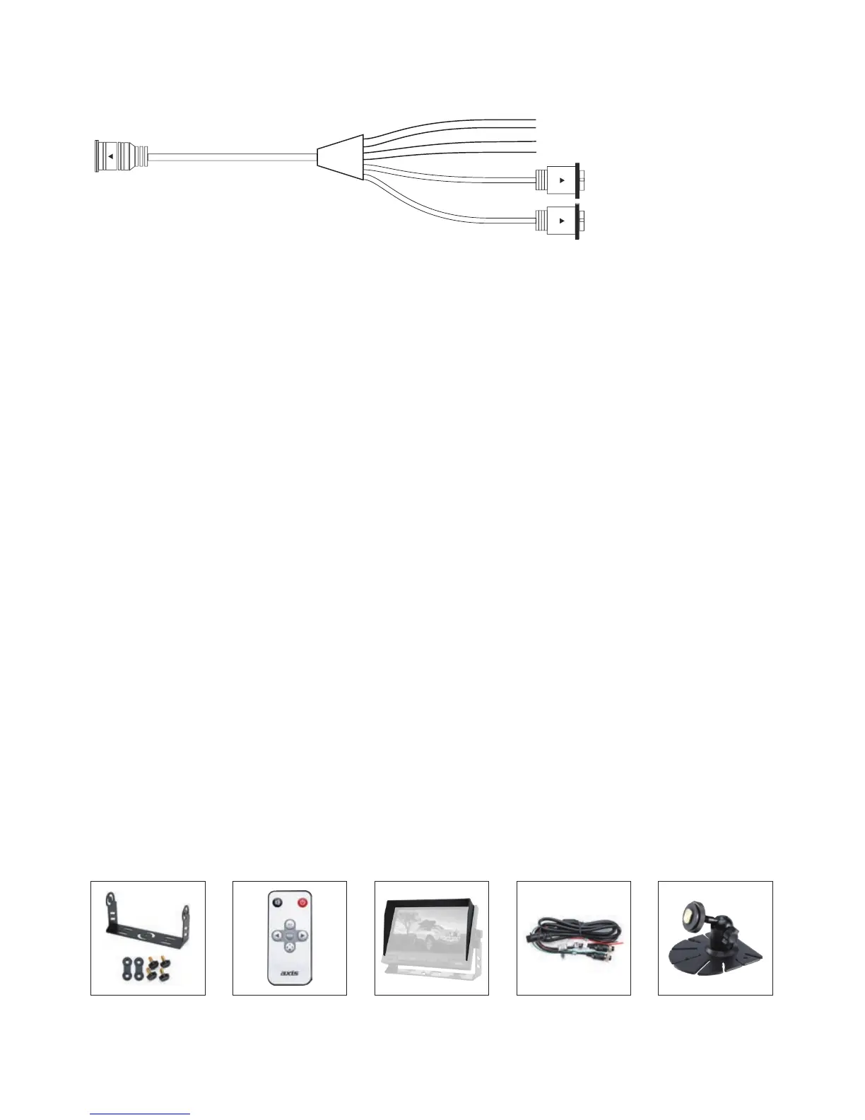
EasyManua.ls Logo

Axis JS5001CK - Installation and Connectivity; System Wiring Diagram; System Accessories Overview

Axis JS5001CK
8 pages
Print Icon
To Next Page IconTo Next Page
To Previous Page IconTo Previous Page
Loading...
5
CONNECTIONS:
Recommended wiring for optimal performance:
• Connect the C20 camera (vehicle camera) to the monitor’s video input (Reverse
trigger switches video input to display on monitor while reversing) and CC10
camera to video input (Caravan camera).
• Connect the reverse trigger wire (green) to the reverse light positive power.
Note:
1. Any input can be selected (CAM Button) when reverse trigger is activated.
2. Reverse trigger can be programmed as CAM 1 or CAM 2 in the menu
(Reverse Priority)
ACCESSORIES:
9 Pin Male
4 Pin Female Video V1
4 Pin Female Video V2
16:9/4:3
1
2
3
4
5
6
7
8
9
10
1. Mute button
2. Power On/Off
3. AV
4. Menu
5. Decrease Button
6. Increase Button
7.
Switch
8. Time switch
9. Display selection
Green - Reverse Trigger
Black - Ground
Brown - Dimmer Control
Red - 12 - 24V
Note: Cam 2 has reverse trigger control.
U-shape Mount Remote Control Sunshade Leads &
Adaptors
Bracket

Related product manuals