6
CAR CAMERA
(C20)
INSTALLATION
1) Determine installation location (usually the centre-rear of vehicle).
a) Buttery Type - Mount on surface using double-sided tape or screws
b) Insert Type - Carefully drill hole (hole saw supplied) in bumper & insert camera
2) Connect RED cable to 12V+ power cable of Reversing Light circuit. (connect to
accessories for constant monitoring if required)
3) Connect BLACK cable to ground.
4) Connect signal extension cable. RCA / 4Pin (M) Patch Lead.
5) Connect RCA (Yellow) video cable to RCA to 4-PIN Adaptor.
6) Connect Adaptor to Monitor (4-Pin Connection)
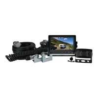
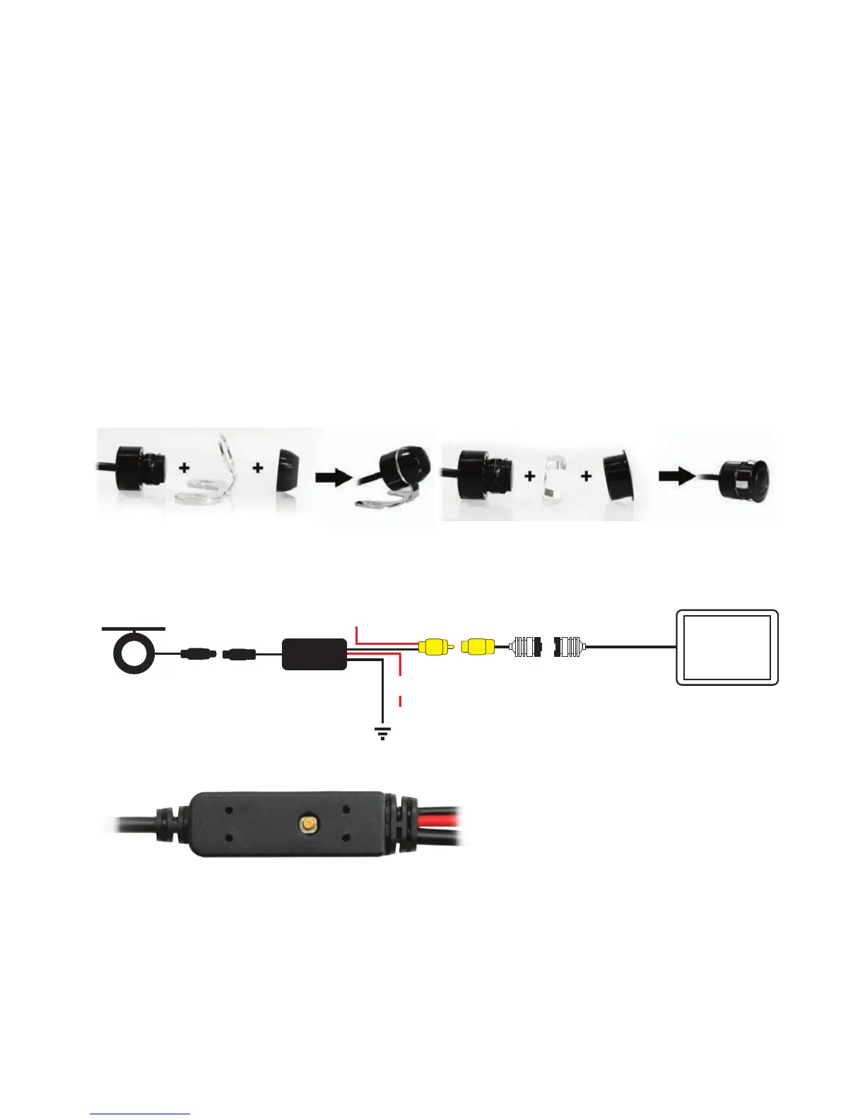
CAMERA ASSEMBLY OPTIONS
The DUAL HEAD system included with your purchase allows for exible installation options, either
surface mount (eg number plate or boot lid) or stealth insert mount (eg bumper).
The RCA video cable simply connects with most aftermarket LCD monitors.
CAR REARVIEW CAMERA
CAMERA ASSEMBLY OPTIONS:
b) Insert Type - Carefully drill hole (hole saw supplied) in bumper & insert camera
16.5mm
CAR REARVIEW CAMERA
CAMERA ASSEMBLY OPTIONS:
See diagram below:
CABLE CONNECTIONS:
See wiring diagram below:
Camera
GND
+12/24V (Red Cable connect to rear lamp positive)
F
F
M
M
Monitor
+
One-Button
Control
ONE-BUTTON CONTROLLER OPERATION GUIDE:
1-click, enter with / without Guide Line switching mode;
THE FOLLOWING MODES MUST BE OPERATED UNDER THE MODE WITH GUIDE
LINE, operate to enter any mode you want 3 seconds after the previous mode.
2-quick-continuous click, enter Mirror / Non-mirror switching mode;
3-quick-continuous click, enter PAL / NTSC switching mode;
4-quick-continuous click, enter Guide Line Type selecting mode;
5-quick-continuous click, enter the Guide Line Width adjusting mode;
6-quick-continuous click, enter the Guide Line Height adjusting mode.
- 12/24 Volt DC
- Dimensions: 16.5mm x 23mm (D)
b) Insert Type - Carefully drill hole (hole saw supplied) in bumper & insert camera
16.5mm
CAR REARVIEW CAMERA
CAMERA ASSEMBLY OPTIONS:
See diagram below:
CABLE CONNECTIONS:
See wiring diagram below:
b) Bumper Fit Assembly
Camera
GND
+12/24V (Red Cable connect to rear lamp positive)
F
F
M
M
Monitor
+
One-Button
Control
ONE-BUTTON CONTROLLER OPERATION GUIDE:
1-click, enter with / without Guide Line switching mode;
THE FOLLOWING MODES MUST BE OPERATED UNDER THE MODE WITH GUIDE
LINE, operate to enter any mode you want 3 seconds after the previous mode.
2-quick-continuous click, enter Mirror / Non-mirror switching mode;
3-quick-continuous click, enter PAL / NTSC switching mode;
4-quick-continuous click, enter Guide Line Type selecting mode;
5-quick-continuous click, enter the Guide Line Width adjusting mode;
6-quick-continuous click, enter the Guide Line Height adjusting mode.
See wiring diagram below:
Camera
GND
+12/24V
(Red Cable connect to rear lamp positive)
F
F
M
M
Monitor
+
One-Button
Control
Monitor Trigger Wire
4-Pin
Male
(Please insulate if not used)
Selectable - Guidelines, PAL/NTSC & Normal/Mirror Image
b) Insert Type - Carefully drill hole (hole saw supplied) in bumper & insert camera
16.5mm
CAR REARVIEW CAMERA
CAMERA ASSEMBLY OPTIONS:
See diagram below:
CABLE CONNECTIONS:
See wiring diagram below:
b) Bumper Fit Assembly
Camera
GND
+12/24V (Red Cable connect to rear lamp positive)
F
F
M
M
Monitor
+
One-Button
Control
ONE-BUTTON CONTROLLER OPERATION GUIDE:
1-click, enter with / without Guide Line switching mode;
THE FOLLOWING MODES MUST BE OPERATED UNDER THE MODE WITH GUIDE
LINE, operate to enter any mode you want 3 seconds after the previous mode.
2-quick-continuous click, enter Mirror / Non-mirror switching mode;
3-quick-continuous click, enter PAL / NTSC switching mode;
4-quick-continuous click, enter Guide Line Type selecting mode;
5-quick-continuous click, enter the Guide Line Width adjusting mode;
6-quick-continuous click, enter the Guide Line Height adjusting mode.
4-Pin
Female
CABLE CONNECTIONS
 Loading...