AXISP1353–ENetworkCamera
TechnicalSpecifications
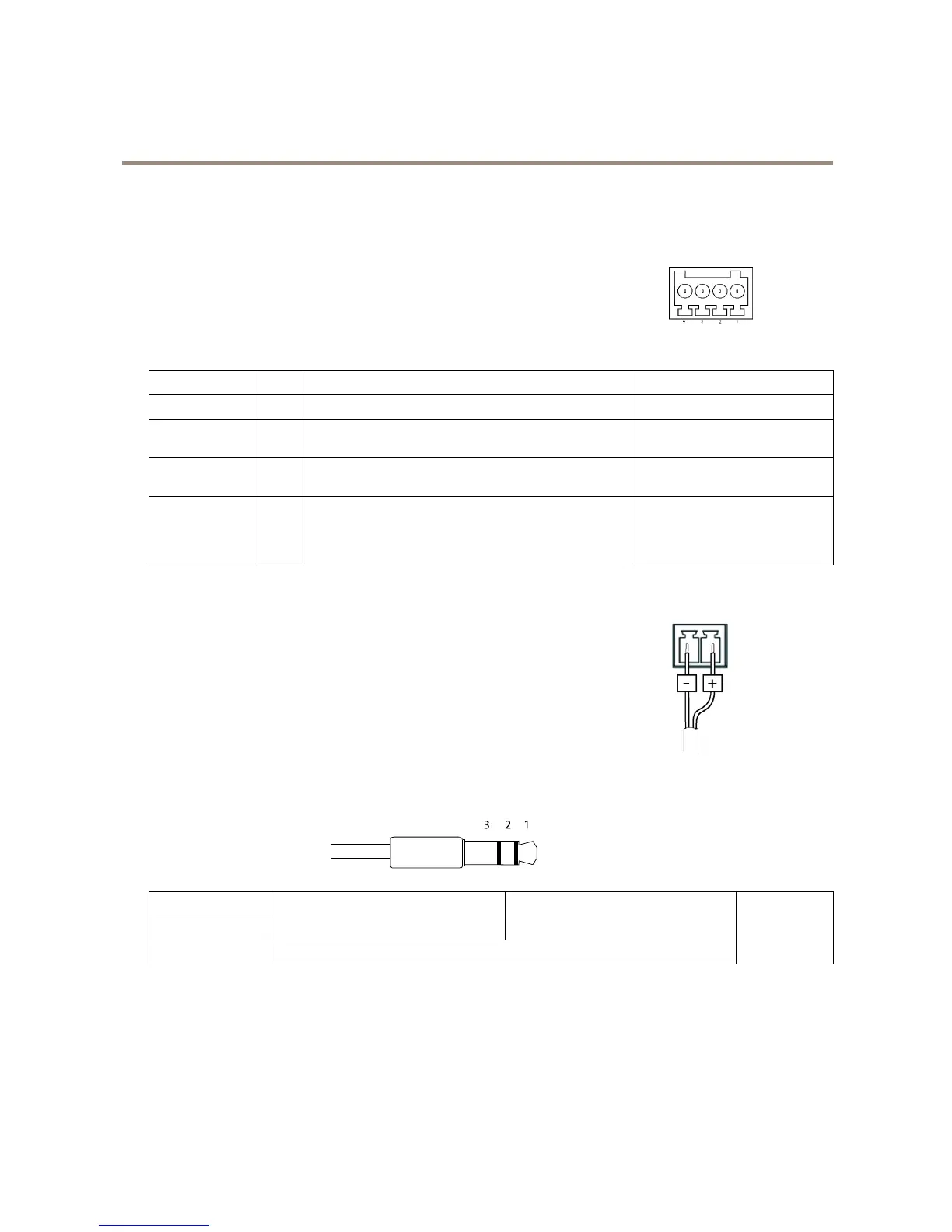
Connectors
I/OConnector
4–pinterminalblock
Foranexamplediagram,seeConnectionDiagramsonpage70.
FunctionPinNotes
Specications
0VDC(-)
1
DCoutput
2
Canbeusedtopowerauxiliaryequipment.
Note:Thispincanonlybeusedaspowerout.
3.3VDC
Maxload=50mA
DigitalInput
3
Connecttopin1toactivate,orleaveoating(unconnected)
todeactivate.
0tomax40VDC
DigitalOutput
4
Connectedtopin1whenactivated,oating(unconnected)
whendeactivated.Ifusedwithaninductiveload,e.g.arelay,
adiodemustbeconnectedinparallelwiththeload,for
protectionagainstvoltagetransients.
0tomax40VDC,opendrain,
100mA
PowerConnector
2-pinterminalblockforDCpowerinput.UseaSafetyExtraLowVoltage(SELV)compliant
limitedpowersource(LPS)witheitheraratedoutputpowerlimitedto≤100Woraratedoutput
currentlimitedto≤5A.
AudioConnector
3.5mmaudioconnectors
(stereo)
 Loading...