AXISP14NetworkCameraSeries
Specifications
1Tip2Ring
3Sleeve
Unbalancedmicrophone(withorwithoutelectret
power)orline
Electretpowerifselected
Ground
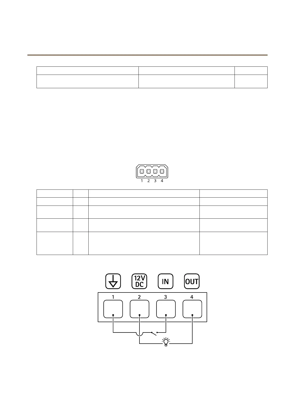
I/Oconnector
UsetheI/Oconnectorwithexternaldevicesincombinationwith,forexample,motiondetection,eventtriggering,andalarm
notications.Inadditiontothe0VDCreferencepointandpower(12VDCoutput),theI/Oconnectorprovidestheinterfaceto:
Digitalinput-Forconnectingdevicesthatcantogglebetweenanopenandclosedcircuit,forexamplePIRsensors,door/window
contacts,andglassbreakdetectors.
Digitaloutput-ForconnectingexternaldevicessuchasrelaysandLEDs.ConnecteddevicescanbeactivatedbytheVAPIX®
ApplicationProgrammingInterface,throughaneventorfromthedevice’swebinterface.
4-pinterminalblock
FunctionPinNotes
Specications
DCground
1
0VDC
DCoutput
2
Canbeusedtopowerauxiliaryequipment.
Note:Thispincanonlybeusedaspowerout.
12VDC
Maxload=25mA
DigitalInput
3
Connecttopin1toactivate,orleaveoating(unconnected)
todeactivate.
0tomax30VDC
DigitalOutput
4
Internallyconnectedtopin1(DCground)whenactive,
andoating(unconnected)wheninactive.Ifusedwithan
inductiveload,e.g.,arelay,connectadiodeinparallelwith
theload,toprotectagainstvoltagetransients.
0tomax30VDC,opendrain,
100mA
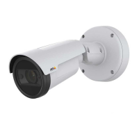
Example
1
DCground
2
DCoutput12V,max25mA
3
Digitalinput
4
Digitaloutput
55