Do you have a question about the Axis Q1615 and is the answer not in the manual?
Defines DANGER, WARNING, CAUTION, NOTICE, Important, and Note levels for risks and information.
Lists sequential steps required for product installation.
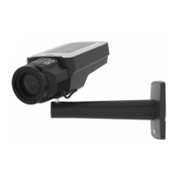
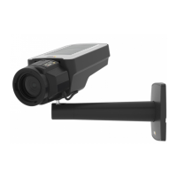
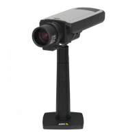
Identifies numbered hardware components shown in the diagram.
Behavior of LEDs and buzzers for Focus and Levelling Assistants.
| Type | IP security camera |
|---|---|
| PTZ control | Yes |
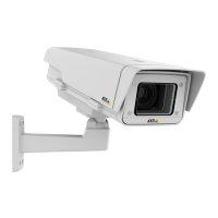
| Placement supported | Indoor & outdoor |
| Connectivity technology | Wired |
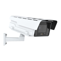
| Form factor | Box |
| Product color | Black |
| Housing material | Aluminium, Metal |
| International Protection (IP) code | IP66 |
| Maximum resolution | 1920 x 1080 pixels |
| Supported video modes | 1080p |
| Video formats supported | H.264, M-JPEG, MPEG4 |
| Camera shutter speed | 1/143000 - 2 s |
| Minimum illumination | 0.18 lx |
| Sensor type | CMOS |
| Optical sensor size | 1/2.8 \ |
| Optical zoom | - x |
| Zoom capability | - |
| Focus adjustment | 1.3 |
| Focal length range | 2.8 - 8 mm |
| Password protection type | User |
| Built-in HDD | No |
| Flash memory | 256 MB |
| Internal memory | 512 MB |
| Compatible memory cards | MicroSD (TransFlash), MicroSDHC, MicroSDXC |
| Maximum memory card size | 64 GB |
| Cabling technology | 10/100Base-T(X) |
| Supported network protocols | IPv4/v6, HTTP, HTTPS b, SSL/TLS b, QoS Layer 3 DiffServ, FTP, CIFS/SMB, SMTP, Bonjour, UPnP ™, SNMPv1/v2c/v3 (MIB - II), DNS, DynDNS, NTP, RTSP, RTP, TCP, UDP, IGMP, RTCP, ICMP, DHCP, ARP, SOCKS |
| Ethernet LAN (RJ-45) ports | 1 |
| Sample rate | 32 kHz |
| Audio system | 2-way |
| Audio formats supported | AAC, ADPCM, PCM |
| Power source type | PoE |
| Operating temperature (T-T) | 0 - 55 °C |
| Operating relative humidity (H-H) | 10 - 85 % |
| Depth | 404 mm |
|---|---|
| Width | 140 mm |
| Height | 58 mm |
| Weight | 914 g |