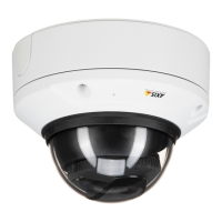
AXISQ3517–LVNetworkCamera
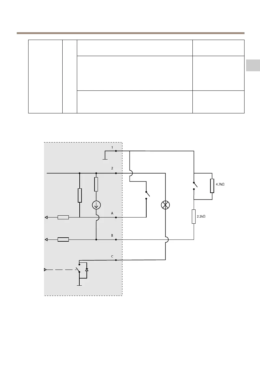
Digitalinput–Connecttopin1toactivate,or
leaveoating(unconnected)todeactivate.
0tomax30VDC
Digitaloutput–Connectedtopin1when
activated,oating(unconnected)when
deactivated.Ifusedwithaninductiveload,e.g.a
relay,adiodemustbeconnectedinparallelwith
theload,forprotectionagainstvoltagetransients.
0tomax30VDC,
opendrain,100mA
Congurable
(Inputor
Output)
3–
4
Supervisedinput–Tousesupervisedinputinstall
endoflineresistors.Seeconnectiondiagramfor
informationabouthowtoconnecttheresistors.
0tomax30VDC
1
0VDC(-)
2
DCoutput12V,max50mA
A
I/Oconguredasinput
B
I/Oconguredassupervisedinput
C
I/Oconguredasoutput
25
EN
 Loading...