AXISQ87BispectralPTZNetworkCameraSeries
I/Oconnectors
UsetheI/Oconnectorwithexternaldevicesincombinationwith,forexample,tamperingalarms,
motiondetection,eventtriggering,andalarmnotications.Inadditiontothe0VDCreference
pointandpower(DCoutput),theI/Oconnectorprovidestheinterfaceto:
Digitaloutput-ForconnectingexternaldevicessuchasrelaysandLEDs.Connecteddevicescan
beactivatedbytheVAPIX®ApplicationProgrammingInterfaceorintheproduct’swebpage.
Digitalinput-Forconnectingdevicesthatcantogglebetweenanopenandclosedcircuit,for
examplePIRsensors,door/windowcontacts,andglassbreakdetectors.
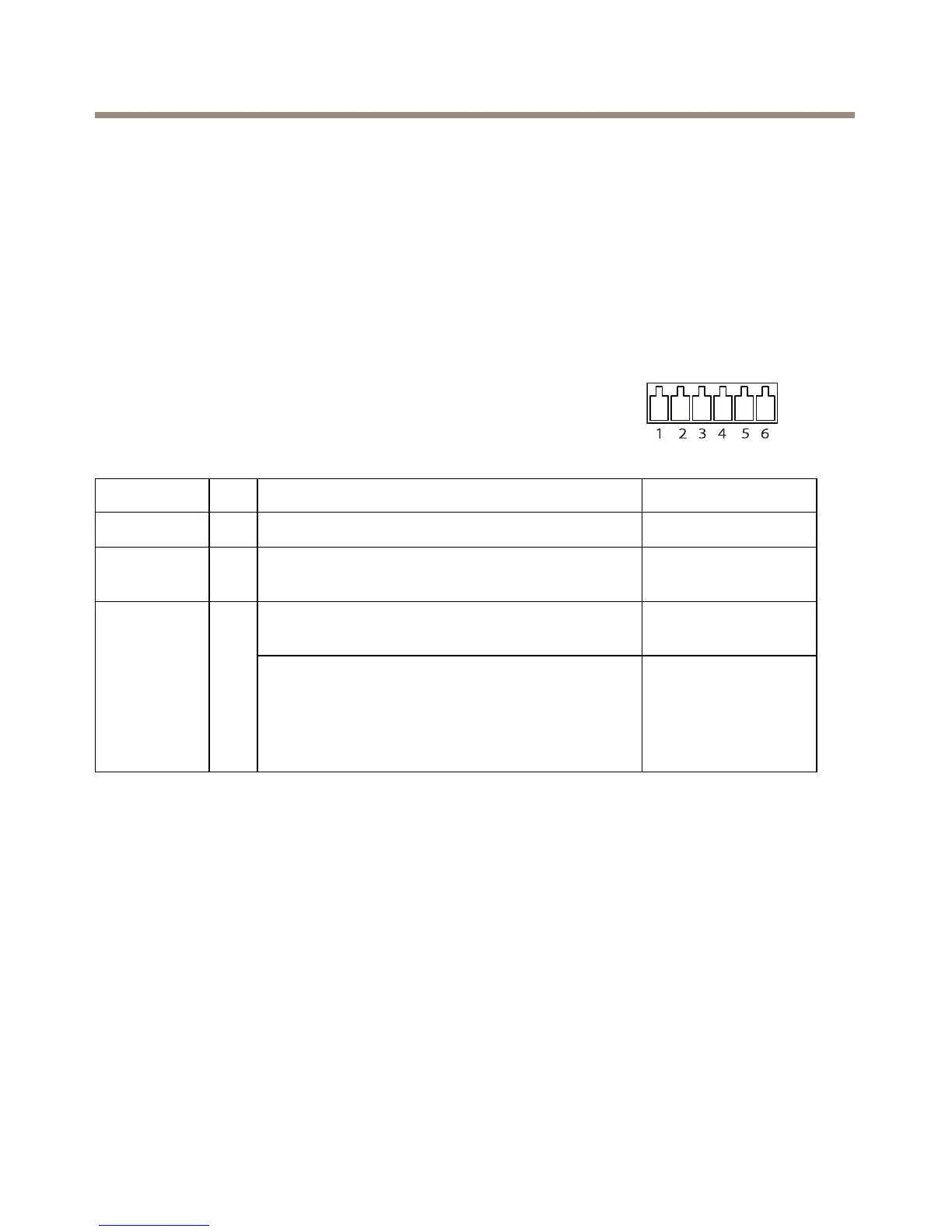
6-pincongurableterminalblock
FunctionPinNotes
Specications
0VDC(-)
1
DCground0VDC
DCoutput
2
Canbeusedtopowerauxiliaryequipment.
Note:Thispincanonlybeusedaspowerout.
12VDC
Maxload=50mA
Digitalinput–Connecttopin1toactivate,or
leaveoating(unconnected)todeactivate.
0tomax30VDC Congurable
(Inputor
Output)
3–
6
Digitaloutput–Connectedtopin1when
activated,oating(unconnected)when
deactivated.Ifusedwithaninductiveload,e.g.a
relay,adiodemustbeconnectedinparallelwith
theload,forprotectionagainstvoltagetransients.
0tomax30VDC,
opendrain,100mA
28