Do you have a question about the Axminster AWHBS350N and is the answer not in the manual?
Essential safety and working practices for operating machinery safely and efficiently.
Attaching the support plate and connecting plates to the base.
Lightly tightening M6 x 12 bolts and washers for cabinet assembly.
Placing the cabinet door and inserting spring hinge pins.
Locating and securing side plates and support plates with bolts.
Screwing the rubber feet into the base of the cabinet.
Tightening all bolts and washers before mounting the bandsaw.
Steps for fitting the saw table, including removing the blade and securing mechanisms.
Instructions for attaching the guide fence and installing the NVR switch shroud.
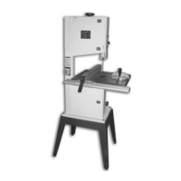
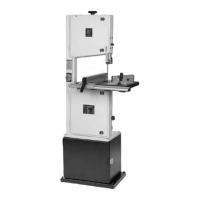
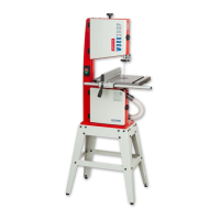
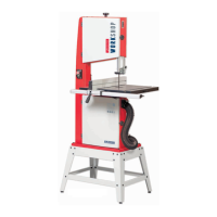
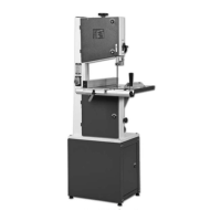
Description of the main body of the machine where other parts are mounted.
Details on the doors covering saw wheel compartments and their interlocks.
Information about the upper saw wheel, its mounting, and function.
Explanation of the blade tensioning wheel mechanism and its operation.
Description of the upper blade guide assembly and its integrated guard.
Details on the clamp used to adjust the height of the upper blade guide.
Description of the saw table, its tilt mechanism, and angle measurement scale.
Description of the power switch and its protective shroud.
Description of the fence used for guiding material during cuts.
Description of the lever used to lock the guide fence in position.
Description of the lower door on the machine.
Description of the shroud covering the power switch.
Description of the main power on and off buttons.
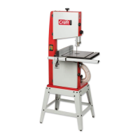
Description of the cabinet base unit for the bandsaw.
Description of the insert that fits into the saw table's groove.
Description of the lower blade guide assembly and its protective guards.
Description of the metal extrusion for the fence and its adjustment slots.
Description of the knob used to raise or lower the upper blade guide.
Detailed description of the extruded aluminium guide fence assembly.
Description of the mitre fence for angled cuts.
Details on the blade tensioning wheel for adjusting blade tension.
Details on the wheel used to adjust the height of the upper blade guide.
Details on the mitre fence for angled cuts.
Description of the mechanism for tilting the saw table.
Description of the clamp used to secure the tilt mechanism.
Description of the housing that holds the tilt quadrant.
Description of the knob for adjusting the idler wheel.
Description of the outlet for dust extraction.
Description of the machine's motor.
Details on the fence used for guiding material during cuts.
Description of the main work surface of the bandsaw.
Description of the scale used to measure table tilt angle.
Description of the pointer for the tilt scale.
Description of the stop mechanism for setting the table to level.
Description of the scale used for setting mitre angles.
Description of the pointer for the mitre scale.
Description of the latch for the upper door.
Instructions for tensioning and tracking the saw blade for optimal performance.
Procedure for ensuring the saw table is perpendicular to the blade.