10
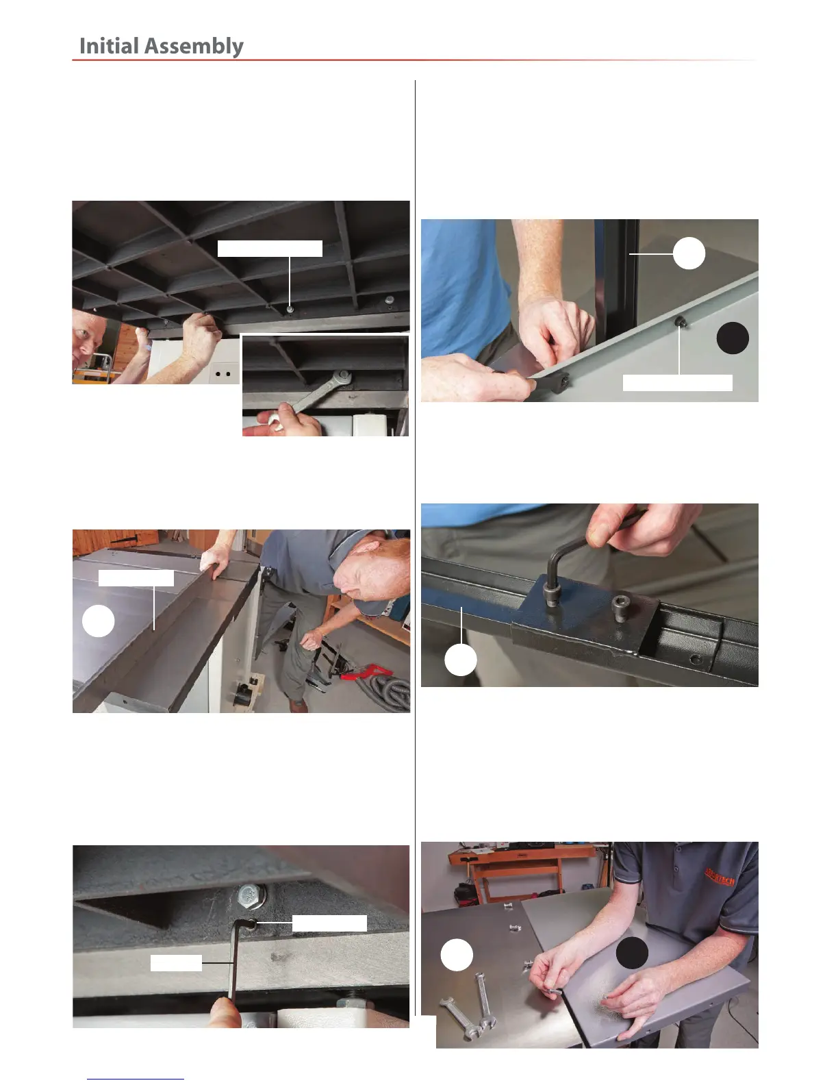
3. Place a straight edge
across both tables and
check they are level with
each other, see fig 12. If there is any deviation between
the tables adjust the four grub screws below each M8
bolt, see fig 13.
Fig 12
NOTE: Make small adjustments (clockwise to raise the
table and anticlockwise to lower the table), checking
as you go, moving the straight edge across the tables
until they are perpendicular. Once you are satisfied
tighten the four M8 bolts.
Fig 11
Fig 13
10
4. Locate the pressed steel table (11) and the support leg
(8), remove the two bolts, washers and nuts from the
support leg, line up the two mounting holes in the
support leg with the two centre holes in the pressed
steel table (11) and secure the leg support to the table
with the fixings you removed earlier, see fig 14.
Grub screw
Hex key
Straight edge
M8 Bolts & washers
2. Offer up the pre-drilled holes in the cast iron table (10)
with the holes in the main saw table (0) and lightly secure
using the four M8 bolts and washers you removed earlier
with the supplied spanner, see fig 11 DO NOT FULLY
TIGHTEN AT THIS POINT.
Fig 14
8
11
Bolts, washers & nuts
5. Loosen the cap head screws and adjust the support
leg (8) length to give you extra support when mounting
the table (11), see fig 15. Retighten when satisfied.
Fig 15
6. Remove the four bolts, washers and nuts from the
pressed steel table (11). Line up the holes in the pressed
steel table with the ones in the cast iron table (10) Insert
the bolts through the pre-drilled holes and lightly secure
with the fixings you removed earlier, see fig 16-17.
Fig 16-17
11
10
8
 Loading...