9
Continues Over....
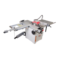
moulding (16) into the round machined cut-out, line up
the pre-drilled holes and secure in place with the fixings
you removed earlier, see figs 01.
2. Open up the side access door and place a hose clip
over the end of the flexible hose, insert the end of the
hose over the extraction moulding and secure in
position, see fig 02-03.
Fig 01-02-03
Extraction moulding
Phillips screw
Flexible hose
Machined cut-out
Hose clamp
Screwdriver
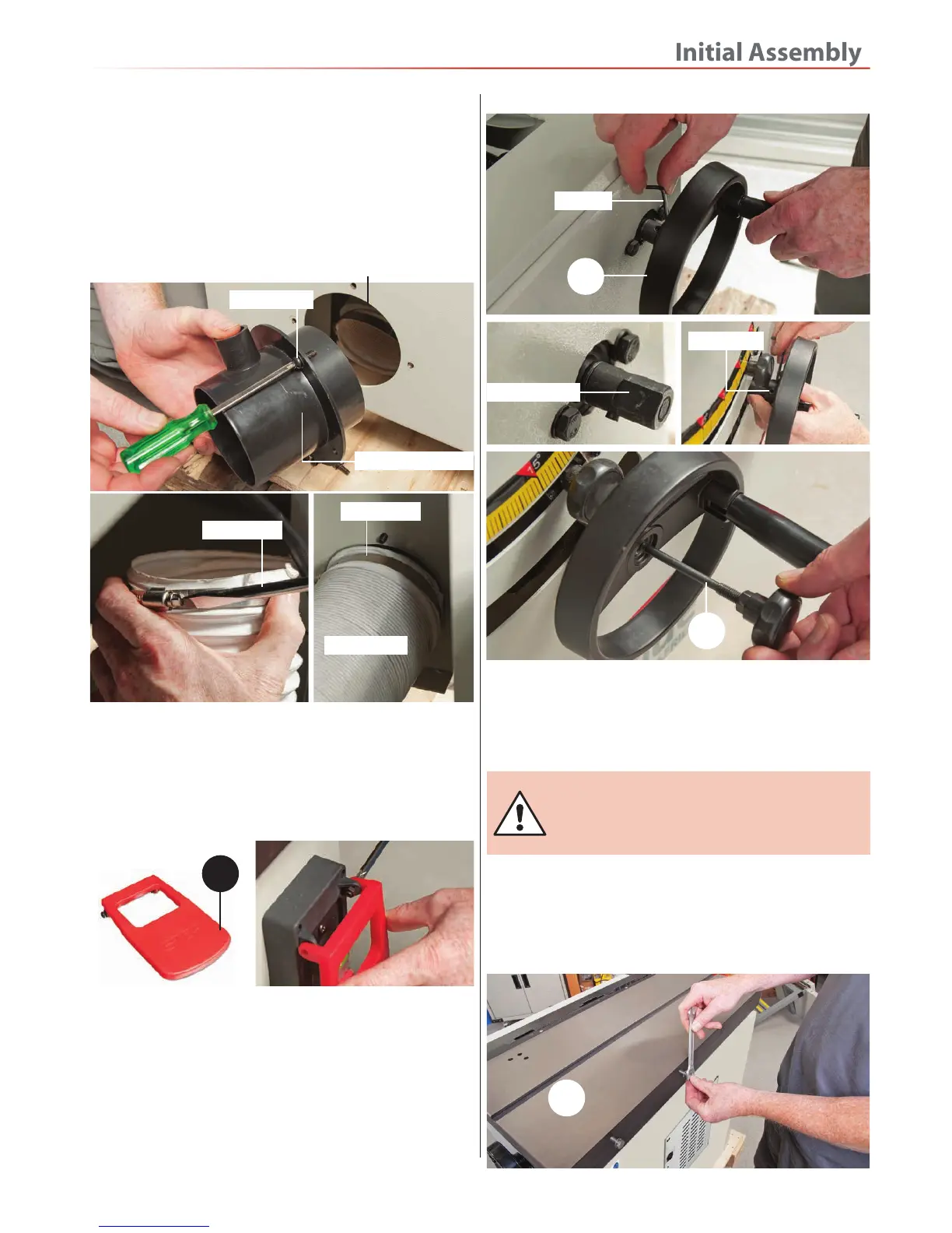
4. Locate the hand wheels (15). Undo the grub screw
with the supplied Hex key to one of the hand wheels
(15), slide the wheel onto the drive shaft and re-tighten
the grub screw. Repeat for the remaining operating
wheel, see figs 06-07-08. DO NOT OVERTIGHTEN
NOTE: Make sure you line up the grub screw with
the machined surface on the drive shaft.
Fig 06-07-08-09
Hex key
15
Machined face
Right Hand Extension Tables
Rise/Full and 45˚ Operating Wheels
WARNING!! THE CAST IRON EXTENSION
TABLE IS VERY HEAVY YOU WILL REQUIRE
A SECOND PERSON TO HELP!
1. Locate the two extension tables (10-11) and the right
hand table support leg assembly (8). Remove the four
M8x25mm bolts and washers from the side of the saw’s
main table (0) and place safely aside, see fig 10.
Fig 10
0
3. Locate the RED emergency stop lever (9) and remove
the two Phillips screws and nuts. Line up the holes in the
hingees with the ones on the NVR switch housing, insert
the Phillips screws through the hingees and replace the
nuts. Lightly tighten sufficiently to allow the lever to
move freely, see fig 04-05.
Fig 04-05
9
Grub screw
5. Locate the locking pin knob (F) and screw locking
knob through the centre of the rise and full operating
wheel, see fig 09.
F
 Loading...