11
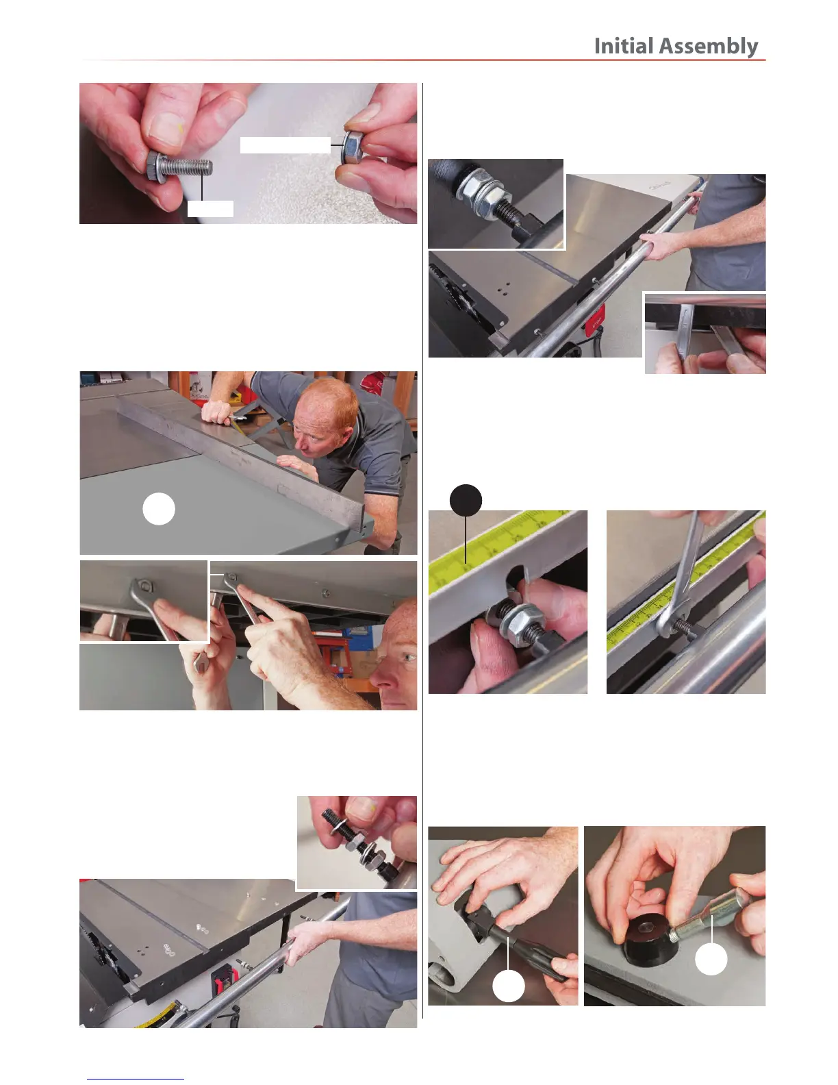
7. Place a straight edge across the tables as before, adjust
the table support leg (8) as described in step 5, until the
pressed steel table (11) is level with the cast iron table
(10), see fig 18. When they are both level clamp the
tables firmly together by tightening the four bolts
beneath the cast iron table, see fig 19-20.
Fig 18-19-20
Rip Fence
Put to hand the rip fence rail shaft (20), rip fence (21), rip
fence scale (24) and rip fence control assembly (2).
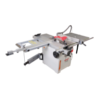
1. Locate the fence rail shaft (20),
remove a nut and one washer from
each of the four threaded studs and
place safely aside, see fig 21.
Fig 21
2. Line up the threaded studs with the pre-drilled holes
to the side of the tables and insert the studs into the
holes, replace the nuts and washers you removed earlier
and tighten, see fig 22.
Fig 22
4. Find the rip fence control assembly (2), the fence
assembly and fence clamping handles (7). Screw on both
handles to the fence control assembly (2), see fig 25-26.
Slide the control assembly (2) onto the fence rail shaft
(20), see fig 27.
Fig 25-26
11
Continues Over....
7
7
3. Locate the rail rip fence scale (24), Adjust the inner nut
to each of the threaded studs to give adequate clearance,
insert the scale slots down over the studs between the
two washers and tighten the nuts to clamp the rip fence
scale (24) in position, see fig 23-24.
Fig 23-24
M8 bolt
M8 Washer/Nut
24
 Loading...