12
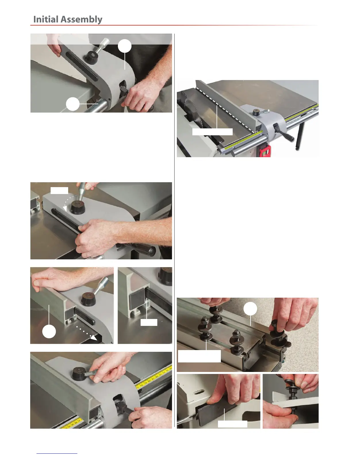
5. Release the clamping handle on top of the control
assembly (2), which releases tension on the clamping
bar, see 28. Line up one of the ‘T’ slots in the rip fence
assembly (21) with the clamping bar and slide the fence
on, see fig 29-30. Position the fence so it’s flush with the
opposite end of the table and tighten the clamping
handle to lock the fence in place, see fig 31.
Fig 28-29-30-31
Unlock
5. Raise the clamping handle on the control assembly (2)
and position the rip fence so it’s in line with the edge of
the main table’s ‘T’ slot, push the handle down to lock in
place, see fig 32. If the fence is out of alignment loosen
Fig 32
the nuts holding the fence rail shaft (20), adjust the shaft
until the rip fence (21) is in alignment. Re-secure the rail
shaft, see 23-24 on previous page.
Main tables ‘T’ slot
Sliding Table
You will require the following, the sliding table
extension support arm (1), sliding table assembly (19),
sliding table fence (23), sliding table extension (13),
sliding table extension support bar (14) mitre fence (3)
for sliding table, workpiece clamp shaft (22) and
workpiece support shoe (4).
1. Remove the four ‘T’ mounting bolts from the
sliding table (19), see fig 33. Remove the two plastic
panels to either end of the machine and loosely secure
the ‘T’ mounting bolts/washers through the four
elongated slots on top of the main saw assembly (0),
see fig 34-35-36
Fig 33-34-35-36
Sliding table
‘T’mounting bolts
20
19
21
‘T’ Slot
Plastic panel
Fig 27
2
 Loading...