14
Fig 47-48
Fig 45-46
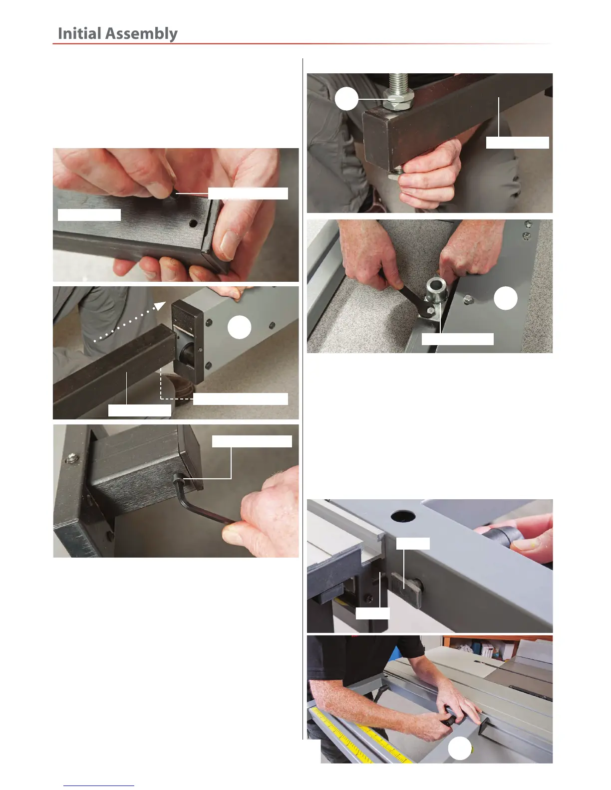
‘T’ slot
‘T’ bolt
13
bar (14). Line up the two ‘T’ bolts on the extension
table with the ‘T’ slots to the side of the sliding table (19)
and slide on the extension table, see fig 47. Lock the
extension table in place with the two lift and shift
handles, see fig 48.
6. Slide the operating handle (I) into the ‘T’ slot from the
right hand side to the front of the sliding table (19), turn
the handle clockwise to tighten, see fig 49-50.
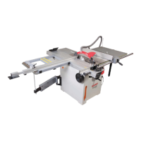
2. Locate the sliding table extension (13). Open up the
supporting arm (1), Remove the caphead screw stop
from the supporting arm extension, see fig 42 and place
aside. Insert the extension through the supporting arm
(1) and replace caphead screw, see fig 43-44.
Fig 42-43-44
Arm extension
Arm extension
Arm extension
Caphead screw stop hole
Caphead screw stop
Caphead screw stop
1
3. Locate the sliding table extension support bar (14),
remove the two nuts from the threaded end and place
aside. Insert the support bar down through the pre-
drilled hole to the end of the supporting arm extension
and lightly secure in place with the two nuts, see fig 45.
4. Remove the mounting bracket from the end of the
supporting arm (14). Turn the table extension (13) over
and remove the two centre bolts/washers. Place the
mounting bracket onto the table and line up the
pre-drilled holes with the ones in the table, secure the
bracket in place with the bolts you just removed, see fig
46.
5. Lower the extension table (13) down so the recess hole
in the mounting bracket inserts down over the support
14
Mounting bracket
13
 Loading...