16
Fig 58-59
Fig 60-61-62
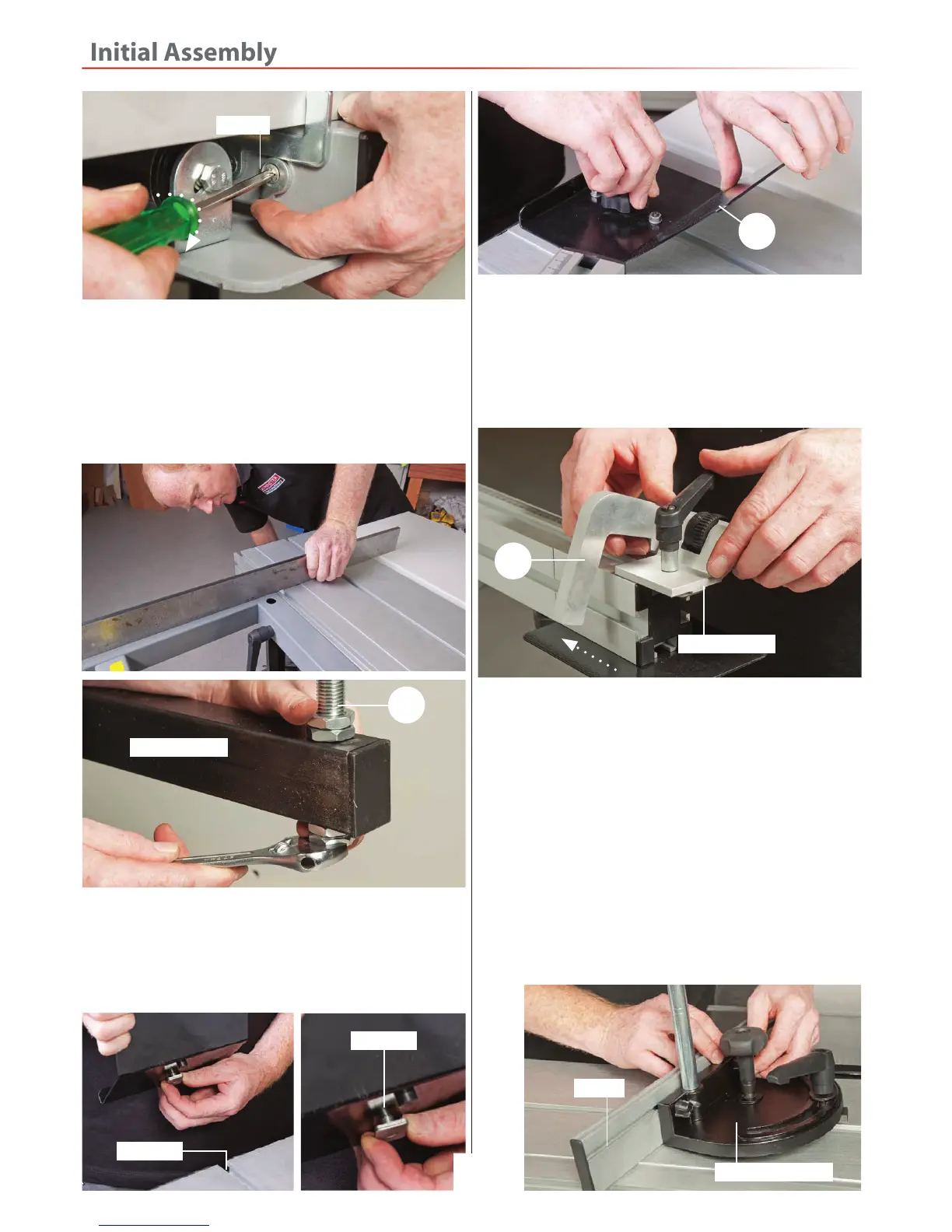
10. Locate the Workpiece support shoe (4), insert the ‘T’
bolt into the ‘T’ slot to the left side of the sliding table
(19), slide the shoe on and clamp in place with the
clamping knob, see fig 60-61-62
4
‘T’ Slot
‘T’ Bolt
12. Locate the sliding table mitre fence (3) which includes
the overhead clamp, the fence and mitre fence casting.
Remove the two butterfly knobs from the fence, inset the
threaded ‘T’ bolts through the two pre-drilled holes in
the mitre fence casting and replace the butterfly knobs.
Lightly tighten,see fig 64.
13. Line up the ‘T’ bolt in the mitre fence casting (3) with
the ‘T’ slot to the opposite side of the sliding table (19),
slide the assembly on until its up against it’s stop, see fig
65-66. The mitre fence should line up with ‘0’ marker on
tables scale, see 67, if not, adjust fence until correct and
tighten the clamping knob and handle.
9. Place a straight edge across both tables and check
they are level with each other, see 58. If there is any
deviation between the tables adjust the nuts on the
supporting arm pin (1), to raised or lower the extension
table (13), see fig 59. Once level tighten the nuts on the
supporting pin.
Cam
11. Locate the sliding table distance stop assembly (23).
Loosen the clamping handle on the distance stop, insert
the ‘T’ bolt into the ‘T’ slot to the end of the telescopic
fence section (23) and slide the distance stop on, see fig
63. Tighten the clamping handle to secure in place.
Fig 63
Fig 64
23
Distance stop
Mitre fence casting
Fence
Arm extension
14
 Loading...