18
Fig 78-79
0
Locate the hose support bracket (B), remove the two cap
head screws, washers, nuts and place close at hand. Line
up the holes with the ones to the rear of the right hand
extension table (11) and secure using the bolts, washers,
nuts you removed earlier, see fig 80-81.
Hose Support Bracket
Fig 80-81
11
B
Cap head screws
Crown Guard & Hose
1. Locate the two 50mm hose clips. Place a hose clip
over one end of the hose, inset the hose over the crown
guards dust extraction outlet and tighten the clip to
secure.
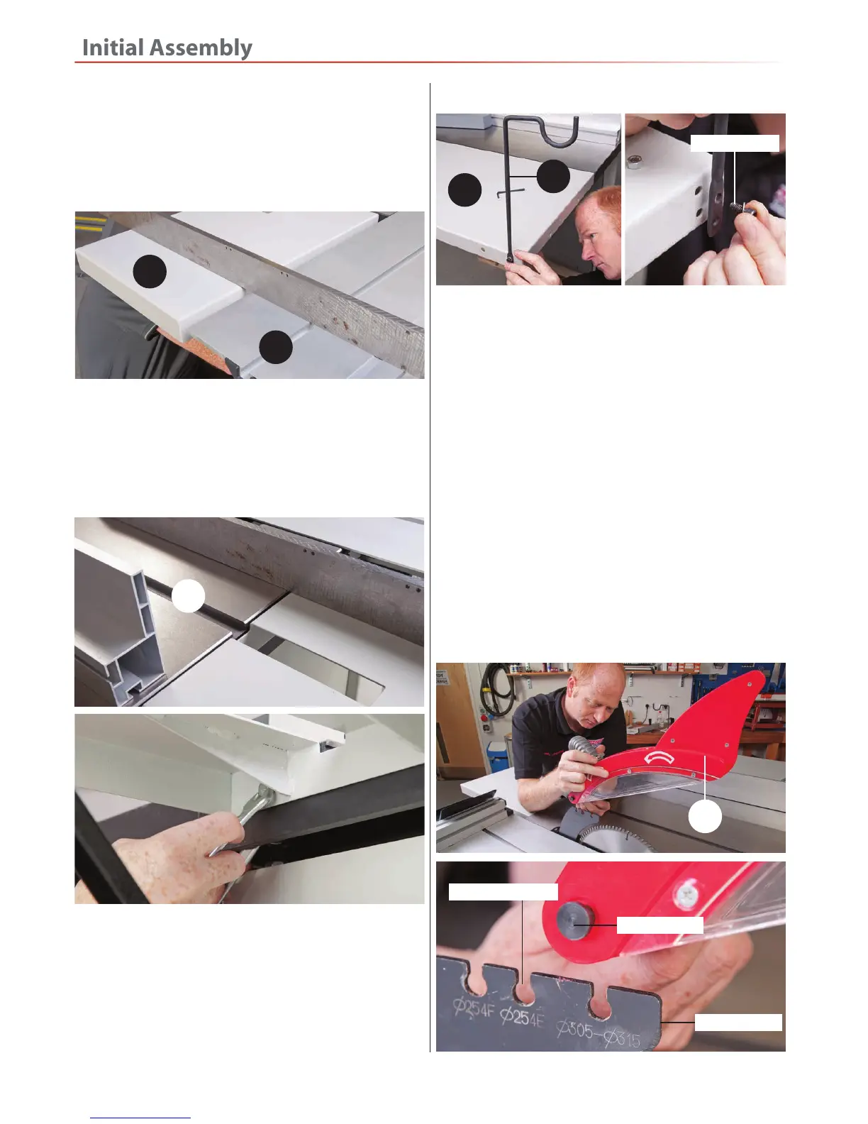
2. Loosen the lift and shift handle on the crown guard
assembly (17), slot the clamping bolt down into the
(315mm) machined cutout in the riving knife and tighten
the handle to secure the crown guard in position, see fig
82-83-84.
Fig 82-83-84
NOTE: Three sizes of saw blades can be fitted to this
panel saw, 254mm, 305mm and 315mm. If you
change your main blade to a different size make sure
to attach the crown guard to the correct position in
the riving knife to allow the crown guard to cover
the blade, see fig 83.
17
Riving knife
Crown guard slots
Clamping bolt
3. Place a straight edge across the rear and sliding tables
(12-19), see fig 77 adjust the rear table (12) until both
tables are level. Securely tighten the threaded bolt to
the side of the machine to lock the table in position, see
fig 74.
Fig 77
19
12
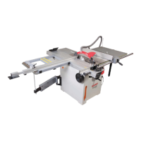
4. Position the straight edge so it’s across the main saw
table (0) and the rear extension table, see fig 78. Adjust
until both tables are level with each other. Tighten the
two bolts to securely clamp the table in position, see fig
79.
 Loading...