Fig 101-102
Saw tip
Fence scale
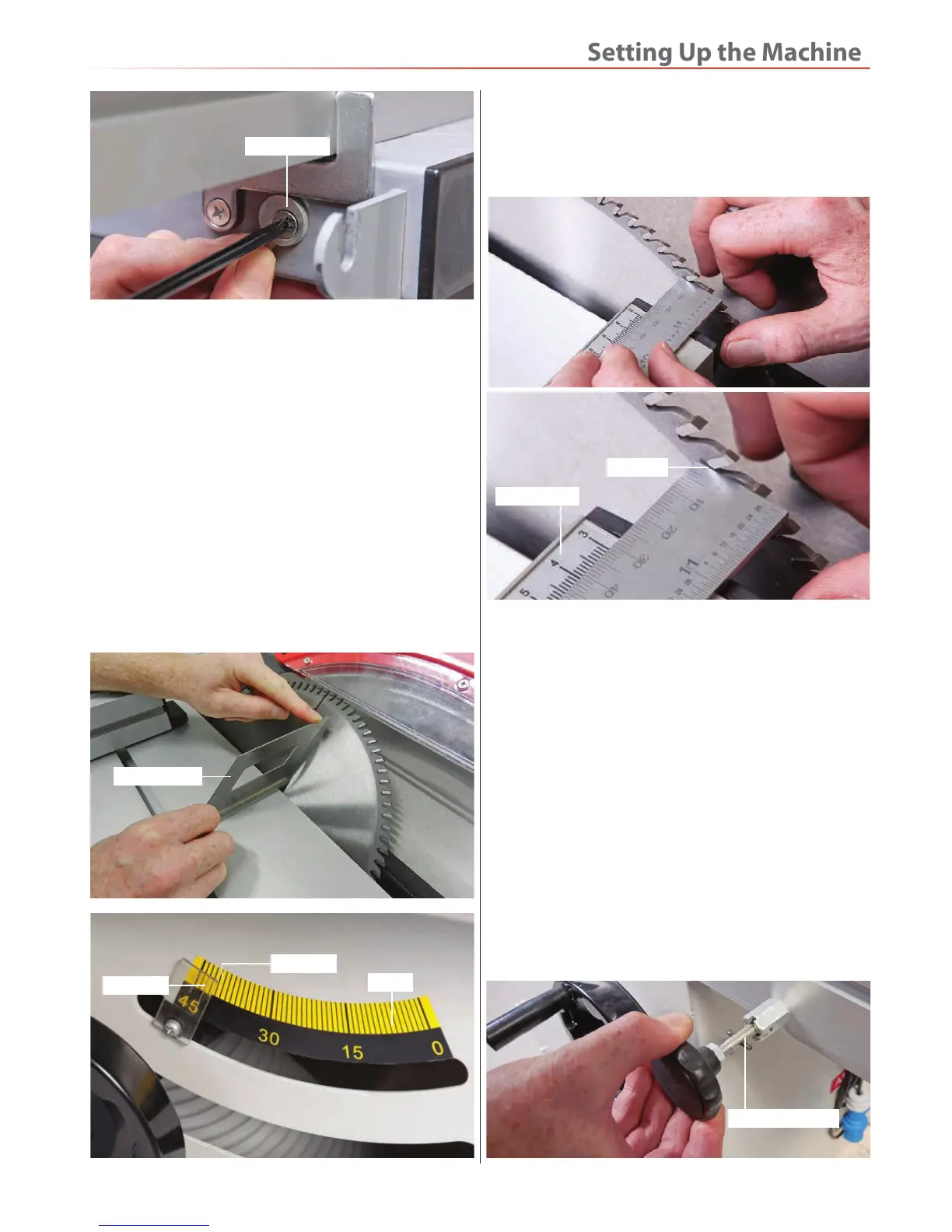
4. Using a steel rule measure 30mm back from the saw
tip, so the scale on the rule lines up with the 30mm on
the fence scale (23), see fig 101-102. Secure the fence
again as described in step 1.
Sliding Table
There should be (0.5 to 2mm) clearance between the
main saw table (0) and the sliding table (19) to allow the
blade to turn freely without it snagging.
1. Raise the saw to it’s highest point and lock the sliding
table (19) in position with the locking pin knob (G), see
fig 103.
2. Using a feeler gauge, loosen the two upper locking
nuts on the mounting bolts below the sliding table (19),
see fig 104 slot the feeler gauge down the gap between
the two tables from one side and adjust until the gap is
set between (0.5 to 2mm), repeat the procedure for the
opposite side, see fig 105.
Table Clearance
Fig 103
Locking pin knob
2. Slide the nose of the fence (the black tongue) up to the
blade, check the parallelity of the sliding table movement
by sliding the table forward and checking the tongue/
blade are still in contact, or that the movement has not
jammed the tongue against the saw. If there is a slight
discrepancy, it may be acceptable to you (a 1mm
difference across the face of the blade (fully extended)
is about one quarter of a degree).
3. Tilt the blade fully over. Using a mitre square, set the
angle of the saw to 45˚degrees. Check that the index
mark gives a corresponding reading against the scale,
see fig 99-100. Adjust the pointer if necessary. Reset the
blade upright, check that the angle scale reading is
correct.
90˚ Stop cam
Fig 99-100
Mitre square
Pointer
Scale
Index mark
 Loading...