14
15
ELECTRICAL SYSTEM CABIN / AC
Your boat is equipped with so-called automatic fuses that pop out when
they go off. Before activating them again, you should check for pos
-
sible reasons why the fuse went off. To activate, press the fuse back
into position.
WARNING! Do not:
•
• carry out electrical installations when the power is switched on
• modify the boat’s electrical system or diagrams; service and
maintenance must be carried out by a qualied electrician
• modify the nominal rated amperage of the overvoltage protector
• install or replace electrical equipment with components that cause
the circuit’s nominal rated amperage to be exceeded
• leave the boat unattended with the electrical system switched on,
except for the automatic bilge pump or alarm system
High voltage system 230V with shore power connection (optional
equipment). The high voltage system comprises the following parts: 230
V 16 A earth fault breaker, 230 V power outlet in the toilet and cock
-
pit, 1 shore power cable.
The shore power system should be checked at least bi-annually. Always
disconnect the shore power cable when the system is not in use. Metal
casings of installed electrical equipment must always be connected to
earth in the boat’s electrical system. Use electrical equipment equipped
with earth protection only.
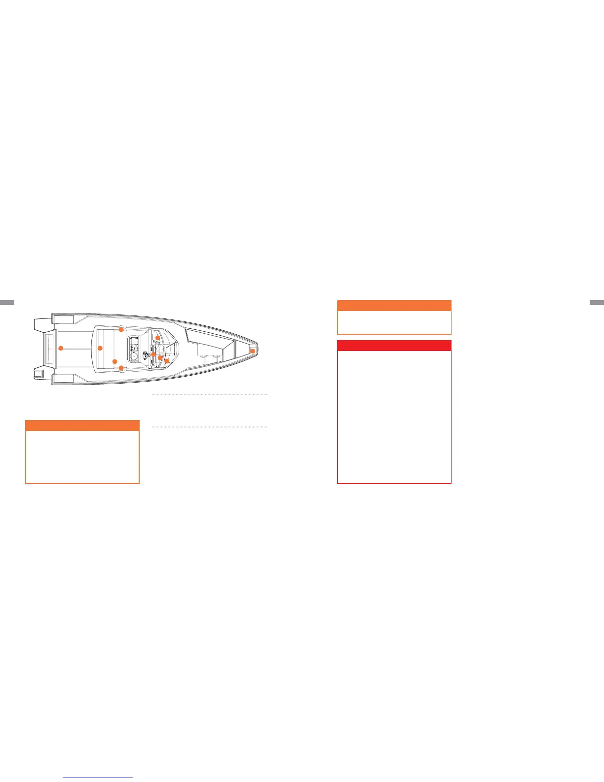
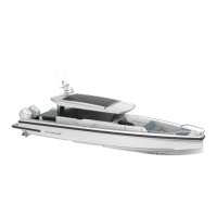
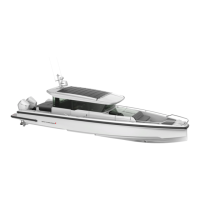
01 Battery compartment
02 Main switch
03 Bilge pump
04 Mast light, white 360°
05 Running lights
06 Switch panel
07 Power outlet 12v. max 10A
08 Fuse box
09 Windscreen wiper
WARNING!
Do not touch an energised high voltage system
Do not modify the shore power cable connectors, only use compatible
connectors
Low voltage system
The boat’s 12 V low voltage system is fed by the service batteries. The
batteries can be disconnected from all circuits using the main power
switches in the electrical panel. With the main power switches on,
power is conducted to the electrical panel and distributed throughout
the boat. The switches for controlling the different functions of the boat
are located on a control panel.
Charging the batteries
Remember that the batteries discharge an explosive oxy-hydrogen gas
at a voltage of 14.4 volts. The voltage of a normal battery in unloaded
status is 12.3-12.7 V. During charging, the voltage increases and the
charging regulator stops the charging process automatically at a pre-set
level. The voltage measurement should be taken at the battery termin
-
als, not the alternator, to achieve the correct result.
Charging status
The best method for determining charging status is to measure the spe
-
cic gravity of the battery acid. This is done using a hydrometer (acid
measurer). Normal specic gravity for a fully charged battery at 20 °C
is 1.26-1.28g/cm³. Note that the specic gravity varies with temperat
-
ure. Batteries from different manufacturers can have a different spe-
cic gravity. Ask your dealer for the correct information. If the specic
gravity varies from cell to cell, then the battery is not in good condition,
and should be replaced. For winter storage, the batteries can be left on
board only if they are fully charged. A partially discharged battery can
freeze and crack. Always disconnect the cable terminals from the bat
-
tery to avoid oxidation.
Cleaning the batteries
The top of the batteries should be cleaned regularly to avoid current
leakage between the cells. If the battery is located in a separate area,
it is normally sufcient to clean it in the spring and autumn. Make sure
that the air holes in the cell plugs are open so that gas can be vented.
DANGER!
• The bleed hoses must be connected after battery replacement or
service. When replacing batteries, marine batteries capable of being
connected to the bleed hoses must be used. The battery isolating
switches are located in the main switch panel. The batteries are
charged when the engines are running, or they can be charged with a
battery charger or other extra equipment.
• Try to minimize the risk of electric shock, short circuit and re.
• Do not allow the shore power cable to hang in the water. If it does, a
hazardous electric eld could be created in the water.
• Switch off the shore power switch before connecting and
disconnecting the cable. Connect the shore power cable to the boat
before connecting it ashore.
• Disconnect the shore power cable ashore before disconnecting it from
the boat. Close the hatch to the shore power socket on the boat.
• Never modify the connections on the shore power cable. Use
compatible connectors only.
• If the earth fault breaker is tripped, disconnect the shore power cable
immediately. In such a case contact a qualied electrician for repairs
before the system is used again.
1
1
6
5
9
3
2
4
7
8