This document describes the AYR 760 Digital Door Viewer, a smart home security device designed to enhance door monitoring with modern features.
Function Description
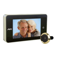
The AYR 760 Digital Door Viewer serves as an advanced replacement for traditional peepholes, offering a digital display and Wi-Fi connectivity for remote monitoring. It allows users to view the outdoor situation on an LCD screen and receive notifications via a mobile application. The device integrates a camera, motion detection, and a call button, providing comprehensive surveillance and communication capabilities for the entryway.
Important Technical Specifications
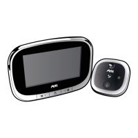
The device comprises two main components: a display unit and an outdoor camera unit.
Display Unit (Indoor):
- Dimensions: 79mm (width) x 110mm (height) x 20mm (depth).
- LCD Screen: 2.8" TFT LCD with a resolution of 320 x 240 pixels.
- Battery: 4300mAh lithium polymer battery.
- Charging Port: USB Type-C, requiring a 5V 1A USB charger. Full charge takes approximately 3.5-4 hours.
- Connectivity: Wi-Fi enabled for app integration.
Camera Unit (Outdoor):
- Dimensions: Ø 60mm (diameter) x 12.5mm (width).
- Sensor: 1.0 Mega Pixel CMOS.
- Image Resolution: 720P (1280 x 720).
- Features: Infrared light for night vision, speaker, call button, motion detection sensor, smart sensor, and microphone.
- Installation Requirements:
- Fits barrel holes with a diameter of 14mm to 35mm.
- Suitable for doors with a thickness between 32mm and 104mm.
- Includes screws of varying lengths (25mm, 50mm, 75mm) to accommodate different door thicknesses:
- 32mm to 54mm door thickness: use 25mm screw.
- 54mm to 79mm door thickness: use 50mm screw.
- 79mm to 104mm door thickness: use 75mm screw.
Usage Features
Power Management:
- Power Button: Press once to turn on the display and view the outdoor situation. Press again to turn off the display and enter standby mode.
Device Configuration and App Integration:
- Pairing Button: Press for a few seconds to enter pairing mode for network configuration and device binding via the "WITH DOOR VIEWER" mobile application. A purple LED will flash at the bottom of the display during pairing.
- Reset Button: Press to restore the device to factory settings.
- App Functionality:
- Registration/Login: Users must register or log in to the "WITH DOOR VIEWER" app.
- Device Naming: Allows users to assign a custom name to the device (e.g., "FRONT DOOR," "BACK DOOR," "OFFICE").
- Installation Video: The app provides a demo video (in English) for installation guidance.
- Wi-Fi Setup: The app guides users through connecting the device to their home Wi-Fi network. This involves leaving the app, accessing system Wi-Fi settings, selecting the device's Wi-Fi network (starting with "WITH-XXX"), returning to the app, selecting the home Wi-Fi network, and entering the password.
- Live View: Once paired, users can access a live view of the outdoor situation through the app.
- Notifications: The app supports call notifications and motion detection notifications.
- Device Status: Displays device health, door status, and allows management of shared users.
Display Interface (Indoor Unit):
- Information Displayed: Date/Time, Wi-Fi signal strength, charging icon, and battery volume indicator.
Maintenance Features
Installation:
- Remove Existing Peephole: If a traditional peephole exists, remove it. If not, drill a 14mm diameter hole at an appropriate height.
- Attach Camera: Select the correct screw length based on door thickness and insert it into the camera. Remove the adhesive protector from the camera's back. Carefully pass the FPC cable through the door hole from the outside to the inside. Stick the camera to the door using its adhesive, ensuring the call button is at the bottom.
- Attach Holding Plate: Remove the adhesive protector from the holding plate. Pass the FPC cable and screws through the holes in the plate. Adjust the plate's position by sliding it to the left to secure the screws and cable in the guides. Stick the holding plate to the door and tighten the screws firmly. Ensure the assembly is securely fixed and the FPC cable is not pinched.
- Connect Display Unit: Connect the FPC cable to the display unit. Carefully bend the excess cable to prevent damage and place it in the cavity on the back of the display unit. Finally, secure the display unit to the holding plate.
Precautions:
- Stability: Do not place the product on an uneven or unstable surface to prevent accidental falls and damage.
- LCD Screen: Do not press hard on the LCD screen or panel to avoid damage.
- Camera Lens/Sensor: Do not squeeze the camera lens or the protruding black motion detection sensor to prevent hardware damage.
- Environment: Avoid placing the product in high-temperature, high-humidity, or hostile environments (dust, salt fog). Do not expose it to rain to prevent malfunction.
- Cable Handling: When installing the display unit, handle it carefully and do not pull the FPC cable forcefully, as this can break the cable and render the unit inoperable. Such damage is not covered by the warranty.
- Product Modifications: The company reserves the right to modify the product's appearance, operating parameters, and usage methods without prior notice.
- Warranty Limitations: The warranty does not cover products used for purposes other than their intended design.
- Environmental Sensitivity: Electronic product parameters may vary in different external environments. These products are intended for use in specific environments.