4
INSTALLATION
1. The Model 2000 analyzer should be located convenient for an operator to read and technician to
install and maintain. A rear rail mounting kit is available for the standard enclosure (see Drawing
IIG01N110). This mounting kit is design for a standard 2” handrail but can be adapted to square
or angle handrails as well.
DO NOT! Locate the analyzer where it is likely to be
damaged during unrelated or other periodic maintenance such
as pressure washing catwalks.
easily mounts to most handrails and slide locks the sensor into place with out the use of tools.
(See drawings IIG02N004, IIG02N005, IIG03N004 and IIG03N005). Again, this sensor mounting
kit is design for a standard 2” handrail but can be adapted to square or angle handrails as well.
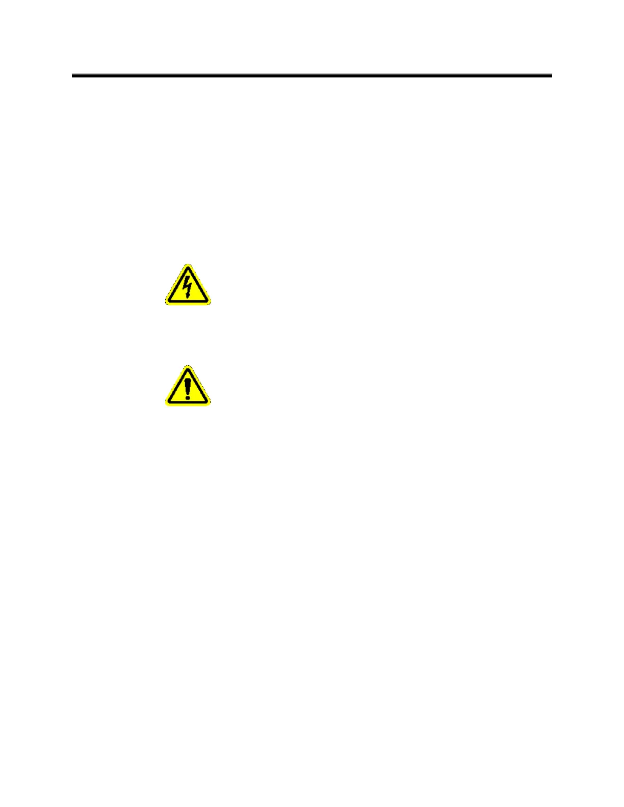
WARNING! – Before opening; switch off
the analyzer line power at the circuit breaker to avoid
risk of shock. Line power is present on terminals even
when analyzer is switched off.
WARNING! – Circuit breaker meeting IEC-
947-3 must be on line supply, in close proximity to
equipment and shall be marked as the disconnecting
device for the equipment.
3. Open the enclosure of the Process Analyzer. Pass all connection cables through glands or ½”
conduit in the bottom of the enclosure (gland and conduit are not supplied). The sensor input
connections are made to terminal blocks TB5 (labeled SENSOR 1) and TB7 (labeled SENSOR 2)
(see drawing IIG04R111). The four wires are color coded and there is a cable shield. Connect the
RED wire to the terminal labeled “RED”. Connect the GREEN wire to the terminal labeled “GRN”.
Connect the WHITE wire to the terminal labeled “WHT”. Connect the BLACK wire to the terminal
labeled “BLK”. Connect the cable SHIELD to the terminal labeled “SHLD”. The analog outputs
are available on the terminal block labeled TB1 and the relay outputs are available on the terminal
block labeled TB6.
4. Power Selector Switch: Check switch S4 on the circuit board to be sure that it is set for the type of
power being used (115 volts or 230 volts). Power connections should now be made to the
terminal block labeled TB3. Turn power "on" by using switch S3. Close and secure the enclosure.
5. Switch the circuit breaker on and the unit will now power up.
6. Once the unit is turned on, the unit will initialize and then jump into the "RUN" mode and begin
displaying Channel 1 “CH 1” content on the upper portion of the display and Channel 2 “CH 2”
content on the lower portion of the display.
2. Mount the sensor in the desired location. Aysix can supply a sensor handrail mounting kit that