E3
■ Wiring
WARNING
Before removing, mounting or wiring this device, be
sure to turn OFF the power to the module and any con-
nected devices. Failure to do so may result in an electric
shock.
Connect the blue signal wire lead to terminal F of the
burner controller and the white lead to terminal G. Also,
before the power is turned on, check that the wiring is
correct. If the power is turned on with incorrect wiring,
the AUD15 will be damaged and a false ame signal will
be generated, endangering combustion safety.
CAUTION
Carry out the wiring work in conformity with the speci-
ed standards.
Connect the power to the equipment as the last step.
Connecting the power sooner may result in electric
shock or damage.
Be sure to route the ame signal wires of this device
separately from high-voltage ignition transformer
cables and power cables. Do not put them in the same
wiring conduit.
● Wiring check
Aer wiring, check that the connections are correct using the
steps below.
• Procedure
(1)
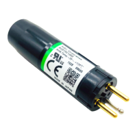
Remove the AUD15 tube unit from the AUD120 socket unit.
(2) Turn on the burner controller.
(3) Measure the DC voltage between hole 3 and hole 1 using a
circuit tester with an input impedance of at least 100kΩ,
or using a digital voltmeter.
Hole No. Tester probe Voltage
3 −
160 to 220 Vdc
1 +
If the reading is between 160 and 220Vdc, the leads are
connected correctly. If the DC voltage reading is negative,
the lead wire connections are reversed.
Blue(F)
White(G)
+ tester probe (red)
- tester probe (black)
Tester or voltage meter
Socket
Hole No.3 (blue)
for negative (-) probe
Hole No.1 (white)
for positive (+) probe
(4) Reinsert the AUD15 one minute or more aer the power to
the burner controller has been turned o.
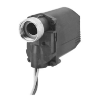
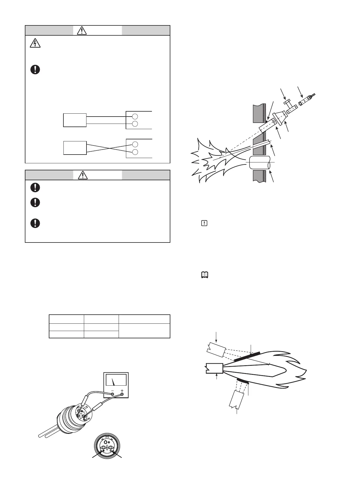
■ Temporary mounting of the monitoring pipe
● Before mounting
Before mounting the ame detector, determine the best posi-
tion according to the user’s manuals provided by the burner or
boiler manufacturer.
e right mounting position is the basis for good combustion
monitoring.
Tee for air purge
Temporary tack weld
Reducer
Monitoring pipe, 50 to 80 A
Pilot burner
Main burner
AUD120
● Mounting angle
Mount the AUD120 so that it monitors the burner at an angle
from above.
Handling Precautions
•If the AUD120 monitors from below or in the same
horizontal plane, dust or soot may accumulate on the
monitoring window or in the monitoring pipe, block-
ing the UV rays and preventing ame detection.
•Insofar as is possible, mount the AUD120 so that it is
parallel to the axis of the ame.
Note
•e greatest quantity of UV radiation is emitted in front
of the burner, near the nozzle.
•e more nearly parallel to the axis of the ame the
monitoring angle is, the greater the area of intersection
between the eld of vision and the ame, and thus the
greater the amount of UV radiation received.
Flame surface area monitored is small.
Detector in poor sighting position
Unburned fuel
Flame surface area monitored is large and
much ultraviolet radiation is detected.
Detector in good sighting position (low angle sighting)
Burner nozzle
AUD120
Burner controller
Blue (F)
White (G)
F
G
AUD120
Burner controller
Blue (F)
White (G)
F
G
Right
Wrong
 Loading...