5
■ Piping
● MCF_ _ _ _ _R pipe installation cautions
• The MCF is a precision instrument. Do not drop it nor subject it to shock.
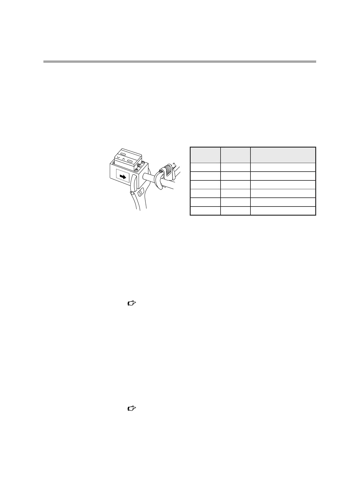
• Install so that the direction of gas flow matches the arrow on the side of the
MCF.
• Do not apply force to the measurement module during installation.
• When attaching the MCF to the pipe, fix the MCF in place and rotate the pipe to
the recommended tightening torque.
• Do not allow foreign matter to enter the MCF. If rust, water droplets, oil mist or
dust from the pipe enters the device, measurement, control error, or damage may
occur. Before installation, be sure to flush the upstream and downstream piping
thoroughly to remove welding fume particulate and dust.
• Coat with an appropriate amount of sealant, but do not coat the top two threads.
Doing so might cause measurement error or damage.
• When connecting a piping element such as a pipe with a different diameter, a
regulator, a filter, or a valve on the upstream side, use the recommended
straight pipe section. Failure to do so could cause a measuring error.
“Accuracy and straight pipe length” (page 9)
• If a reducer or tube fitting is connected without a straight pipe section, the dis-
play might indicate a negative flow rate even though air is flowing in the posi-
tive direction.
“Straight pipe section” refers to a straight pipe with the same diameter as the
MCF port. The following types of pipe are suitable: Carbon Steel Pipes for
Ordinary Piping (JIS G3452), ANSI schedule 40 or less; Carbon Steel Pipes
for Pressure Service (JIS G3454), or ANSI schedule 40 or less; Stainless Steel
Pipes (JIS G3459).
• Although there are no restrictions of mounting direction, if the MCF is mounted
on a horizontal pipe and the display faces to the side, a measuring error can be
caused by the mounting direction.
“Mounting direction” (page 7)
Also, if the unit is mounted on a horizontal pipe with the display facing down-
ward, foreign matter (rust, water droplets, oil mist, dust) in the pipes might accu-
mulate in the sensor, causing measuring error or damage.
• Do not install this device near the outlet of a compressor or bellows pipe, or in a
location where the regulator and the check valve cause a hunting phenomenon.
Doing so could cause measurement error.
Chapter 3. MOUNTING AND WIRING
Model Pipe Recommended tightening
number size torque [N•m]
MCF0080 1/4 inch 12 to 14
MCF0150 1/2 inch 31 to 33
MCF0151 1/2 inch 31 to 33
MCF0250 1 inch 36 to 38
MCF0400 1 1/2 inch 59 to 61
MCF0500 2 inch 74 to 76