4
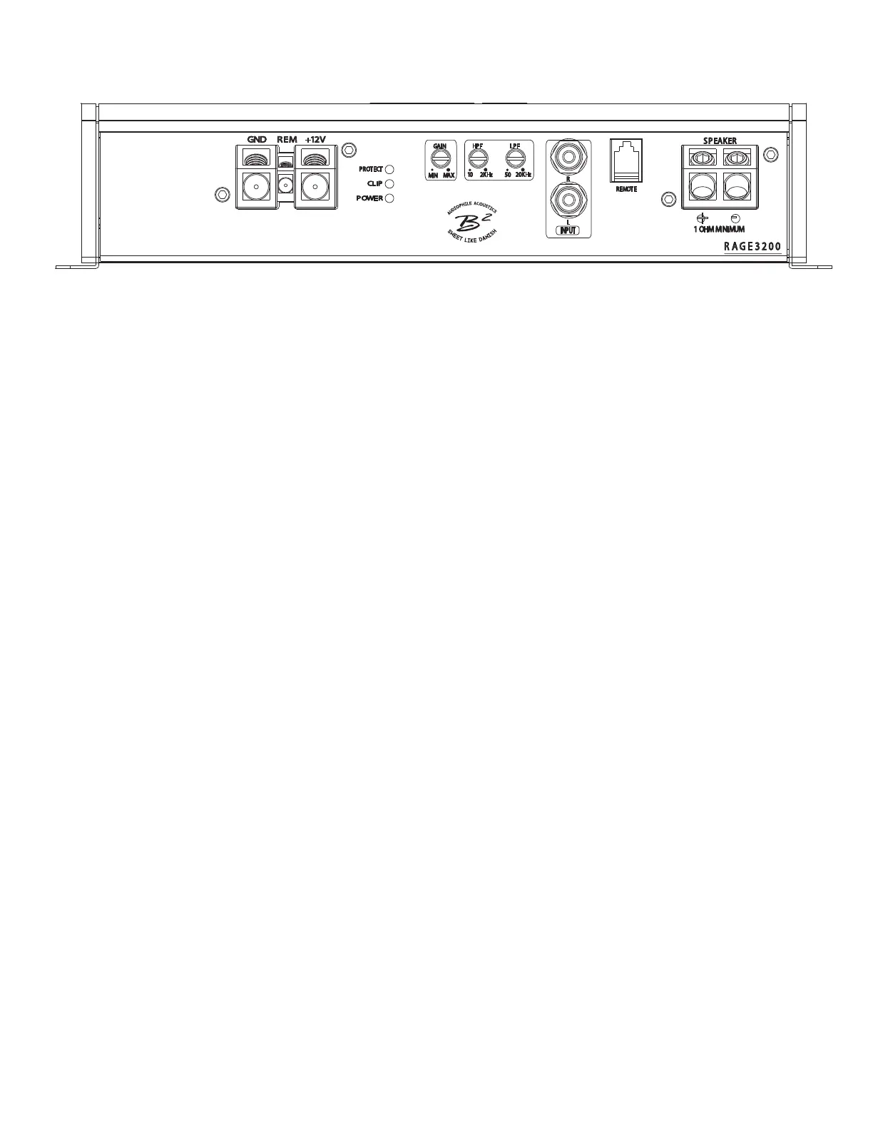
Panel layout
Rage 1500 / rage 3200
gnd (Ground connection) Rem (+12v switched)
Connects to the vehicle’s chassis. Keep as short as possible Switched 12v connection from source unit. It is adviseable
(<20”/ 50 cm) Using wire with a maximum gauge specied to use a common relay to ensure a stable voltage connection
to the terminal ensures optimal operation. without dips.
+12v (power connection) led indicators
Connects to the positive terminal of the battery. For Power lit, amplier is operational and on.
optimal performance, use wire specied to the power Clip ashing shows the signal is not clean at peaks. Clip lit,
terminal. Fuses shall be placed within 8” / 20 cm of the signal is heavily distorted. The loudspeaker & the amplier
battery. can be damaged over time. Protect lit, the amp has shut o.
Could be caused by install, thermal shutdown, short circuit,
low voltage & circuit damage to the pcb.
Gain (6v~0.2v) HPf (12 db/oct)
Adjusts signal input voltage from the input source to match Variable high pass crossover from 10 Hz to 2 KHz.
the ampliers input stage. 6V ~ 0.2V is the voltage range. It is highly recommended to set it according to the tuning
Sudden voltage spikes or voltages beyond the above may of your loudspeakers enclosure / t/s parameters to
cause errors or damages to the input section. Eventually avoid unnecessary strain to your sound system.
the amplier can go into protect. It is advisable to use a
low (< 1V) input if the amplier is driven into a low ohm
lPf (12 db/oct)
load. Variable low pass crossover from 50 Hz to 20 KHz, if used with
HPF, it will create a bandpass cong.
input remote port
RCA input signal from the source unit. Use a signal of min Connection of external level controller with voltmeter &
0.3V ~ 6V max to ensure proper operation. clipsensor. Caution, it is not a volume knob & shall be
adjusted in accordance with the ampliers gain.
speaker output
2 pin layout speaker terminal. Do not attempt to bridge
externally. The minimum load is 1 Ω.
Any connection below 1 Ω is not warranted. The amp can’t be
strapped or bridged in any way either.
This circuit design will have a high output voltage on BOTH
speaker terminals, even after the amplier has been shut of
for a while. For any connections or changes in conguration,
do measure if voltage is still present prior to doing so. This
will avoid potential shorted circuits.
GND
REM
+12V
POWER
PROT ECT
CLIP
REMOT E
+
-
S PEAKER
MIN
MAX
G
AIN
2KHz
2
0KHz
HPF LPF
10
5
0
INPUT
R
L
R A G E 3 2 0 0
1 OHM MINIMUM
 Loading...