Do you have a question about the b2 electronic PD Series and is the answer not in the manual?
Guideline indicating significant information based on user responsibilities.
Explains safety symbols and signal words used in the document.
Explanation of hazard, forbidden practice, and precautionary symbols.
Details warranty, contact information, and copyright.
Notice regarding the operation manual and its importance for high voltage tests.
DANGER: Electric Shock Hazard and essential safety procedures for handling equipment.
Lists appropriate DUTs and measurements for the PD test instrument.
Mandatory requirement for qualified electrical technicians and rescue training.
Explains how high voltage cables act as waveguides for PD pulses.
Details the PDTD-2 system for cable, machine, and transformer diagnostics.
Lists technical specifications for various PD units and Tan Delta measurements.
Details shipment content, specific product accessories, and optional items.
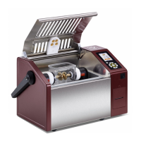
Illustrates the design and construction of PD units and related components.
Diagrams and descriptions of connections for earthing, HV, communication, and buttons.
Details remote control via b2 Suite software and necessary cables.
Describes PD operation modes: Test Modes, Output Modes, Data Transfer Modes.
Diagram and procedure for PD measurement setup using the PD30-E unit.
Diagram and procedure for PD measurement setup using PDTD-2 CC and PD-2 Filter.
Diagram and procedure for PD and TD measurement setup using PDTD-2.
Diagram and procedure for PD/TD measurement with extension cable and leakage correction.
Diagram and procedure for PD measurement without leakage current correction.
Diagram and procedure for PD measurement with extension between Filter and CC.
Diagram and procedure for PD measurement using guard compensation.
Diagram and procedure for PD measurement setup using PDTD200-2.
Diagram and procedure for setting up the PD calibrator.
DANGER: Electric Shock Hazard - procedures for safe disconnection of equipment.
Precautionary measures and procedures for disconnecting during testing errors or power loss.
Diagram and procedure for disconnecting PDTD-2 from a PD measurement setup.
DANGER: Electric Shock Hazard - instructions for cleaning the instrument safely.
CAUTION: Instrument Damage - guidelines for proper storage conditions of PD Systems.
NOTICE: Repairs and maintenance must only be performed by authorized personnel.
| Filtering | Band-pass and notch filters |
|---|---|
| Software | Included for data analysis and reporting |
| Communication Interface | USB, Ethernet |
| Operating Temperature | 0°C to +40°C |
| Dimensions | Varies depending on the model and configuration |
| Weight | Varies depending on the model and configuration |
| Storage Temperature | -20°C to 70°C |