Do you have a question about the Baby Lock BLE1 AT and is the answer not in the manual?
Covers adjustments for lower looper height and presser foot height.
Details adjustments for the upper looper and needle guard.
Procedure for timing the tension discs for open-shut function.
How to adjust clearance for thread press post arm.
Steps to replace the timing belt of the thread delivery unit.
Steps to replace the entire thread delivery unit assembly.
Instructions for replacing springs within the thread delivery unit.
Guide for replacing sensor cables for thread detection.
Adjusting the needle thread sensor cable for stitch balance.
Adjusting the looper thread sensor cable for stitch quality.
Steps to replace the needle threader component.
Adjusting the vertical direction of the needle threader.
Adjusting the horizontal direction of the needle threader.
Adjusting the needle threader safety plate.
Procedure to check for air deflation from the pump.
Steps to replace the piston cap of the pump.
Diagnosing and fixing unbalanced needle threads.
Diagnosing and fixing unbalanced looper threads.
Troubleshooting common causes of thread breaks.
Addressing issues with the needle threader's functionality.
Troubleshooting the jet air threader when it fails to operate.
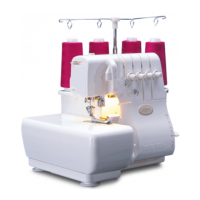
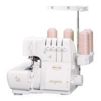
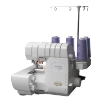
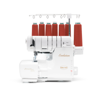
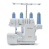
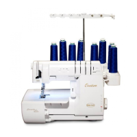
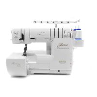
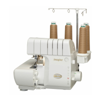
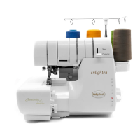
This document is a service manual for the Baby Lock BLE1AT sewing machine, providing detailed instructions for its maintenance, adjustment, and repair. The manual covers various aspects of the machine's operation and upkeep, ensuring optimal performance and longevity.
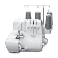
The Baby Lock BLE1AT is a sewing machine designed for various stitching tasks, featuring an advanced thread delivery system (ATD) that simplifies threading and ensures consistent stitch quality. The machine is equipped with multiple components that work in harmony to produce precise and durable seams. Key functional areas include the needle, lower looper, upper looper, chain looper, and presser foot, all of which require precise adjustment for optimal operation. The ATD system, a core feature, manages thread tension and delivery, crucial for achieving balanced stitches across different fabric types.
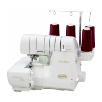
The Baby Lock BLE1AT is designed for ease of use, particularly with its threading system. The machine utilizes a quick threading reference guide to assist users in correctly threading the various components. The ATD system aims to minimize common threading issues, such as thread tangles and inconsistent tension, which are often a source of frustration for users. The stitch selector dial allows users to choose different stitch types, enhancing the machine's versatility for various sewing projects. The machine's design also considers the positioning of sensor cables and rollers, which are critical for the ATD system's functionality, ensuring that threads are delivered smoothly and accurately. The presser foot height and needle guard adjustments are also important for proper operation, allowing users to adapt the machine to different fabric thicknesses and ensure safety during use.
The service manual provides comprehensive instructions for maintaining the Baby Lock BLE1AT, focusing on adjustments and replacements of critical components.
Before any adjustments to the ATD system, it is crucial to check several items to ensure proper function. These include verifying that the thread is correctly positioned between the discs, the spring in the head thread guide catches the thread properly (noting that the BLE1AT's head thread guide is exclusive to this model), sensor cables are positioned on rollers (especially the one behind the fine-tuning screw), the stitch selector dial is correctly positioned, and each thread is threaded according to the quick threading reference guide.
Open-Shut Timing of Tension Discs: Correct timing is achieved when the front tension discs are perfectly shut when the upper looper is in its lowest position. To adjust this:
Clearance for Thread Press Post Arm: The correct clearance for both front and rear thread press post arms is 0.4mm.
Rear Clearance Adjustment (Adjust first):
Front Clearance Adjustment:
The manual details how to replace the stitch connecting arm plate spring, looper thread pulling plate spring, thread pulling movable spring, and disc press spring. Each replacement involves specific steps, such as hooking springs on both sides, removing fixing screws, and carefully handling E-rings and shafts to avoid splashing springs.
The Baby Lock BLE1AT uses three types of sensor cables: fabric thickness, needle thread, and looper thread. These cables are made of fine stainless wire with a high pulling strength, making replacement infrequent. However, if replacement is necessary, specific instructions are provided for each type, including removing the old cable, hooking the new one, and checking stitches afterward.
For optimal stitch quality, adjustments are made based on fabric type (cotton 1-layer), thread (100% polyester spun), needle (SCHMETZ HAX1SP #11/CR), machine settings (1-needle, 3-thread sewing, 5.0mm width, 3.0mm length, D.F.: N, stitch selector: B).
Needle Thread Sensor Cable Adjustment: This adjustment affects both needle and looper threads.
Looper Thread Sensor Cable Adjustment: This adjustment should be done after the needle thread sensor cable.
Before adjusting the needle threader, new SCHMETZ HAX1SP #11CR needles must be installed and correctly positioned in the needle clamp holder, as bent or incorrect needles can cause timing issues.
Replacement of Needle Threader:
Adjustment of High and Low Direction for Needle Threader:
Adjustment of Right and Left Direction for Needle Threader:
Adjustment of Needle Threader Safety Plate:
Checking Deflate from Pump: Hold the pump tube, push down the pump lever, and check if air is deflated from the pump.
Replacement of Piston Cap:
The manual includes a troubleshooting section for common issues:
Needle Threads Unbalanced: Check if the serger is threaded correctly, threads are snapped in the head guide, stitch selector is positioned correctly, looper thread fine-tuning screw is positioned correctly, threads are of recommended high quality, needle thread sensor cable is positioned correctly, and needle thread sensor cable is adjusted correctly.
Looper Threads Unbalanced: Similar checks as for needle threads, focusing on the looper thread sensor cable's positioning and adjustment.
Thread Breaks: Verify correct serger threading, proper thread snapping in the head guide, correct stitch selector position, correct looper thread fine-tuning screw position, and recommended thread quality.
Needle Threader Works Improperly: Check if green marks on the pulley and machine body are aligned, needles are inserted to the end of the clamp holder, height of each needle is correct, and needle threader adjustment is correct.
Jet Air Threader Does Not Work: Check if air is deflated from the pump, pipes are connected properly, and there are no lints or threads in the pipes.
This comprehensive approach to maintenance and troubleshooting ensures that the Baby Lock BLE1AT can be kept in optimal working condition, providing reliable performance for all sewing needs.
| Free Arm | Yes |
|---|---|
| Needle Threading System | Automatic |
| LCD Screen | Yes |
| Connectivity | USB |
| USB Port | Yes |
| Type | Embroidery |
| Model | BLE1AT |
| Max Stitch Width | 7 mm |
| Max Stitch Length | 5 mm |
| Differential Feed | Yes |
| Weight | 22 lbs |
| Dimensions | 20.5 x 16.5 x 14.5 inches |
| Maximum Embroidery Area | 6.3" x 10.2" (160mm x 260mm) |
| Built-in Embroidery Designs | 136 |
| Built-in Sewing Stitches | 191 |
| Stitch Length | 0.0 - 5.0 mm |
| Stitch Width | 0.0 - 7.0 mm |
| Presser Feet | 7 |