5.2 Replacing the Printed Circuit Board
Items required:
• Medium fl at-blade screwdriver
• Medium Phillips screwdriver
• Replacement printed circuit board (P/N 0019-0418)
Procedure: (See Figure 7)
1. Turn OFF instrument and lay it face down on work area.
2. Remove battery cover and batteries.
3. Remove sensor-matching resistor.
4. Remove four screws securing rear case.
5. Carefully lift rear case and fl exible arm assembly away
from instrument, being careful not to pull wires attached
to printed circuit board. Lay rear case face down on work
area.
6. Carefully remove printed circuit board from front case.
7. Unplug connectors J2 and J3 from printed circuit board.
8. Plug connectors J2 and J3 into new printed circuit board;
then install board into front case.
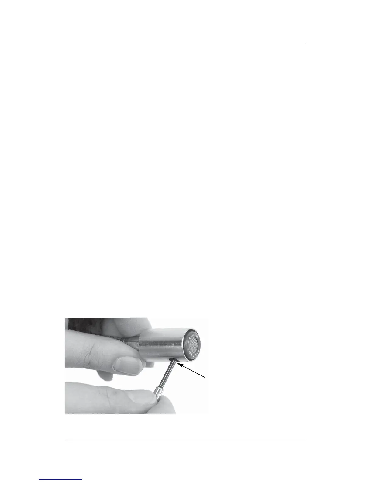
Figure 4. Removing Sensor
Maintenance
10
Leakator 10
Instruction 0019-9167
Pry sensor from its socket
using a small flat-blade
screwdriver inserted
throu
 Loading...