Maintenance
15
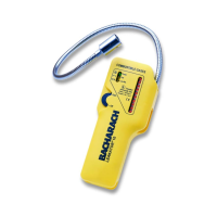
Leakator 10
Instruction 0019-9167
6.0 TROUBLESHOOTING
WARNING!
Do not perform any maintenance work in a
hazardous area.
Because of the Leakator 10’s advanced design, trouble with the
instrument can usually be diagnosed by looking at the LEDs
as seen through the front-case. See Figure 3.
If the Fail LED lights, check that the sensor is seated and J3
is connected to the printed circuit board. If still no change,
replace the sensor per Section 5-1 Replacing the Sensor.
If the Low-Bat. LED lights, replace the batteries per Section 3.0
as soon as possible. The instrument should operate, however,
for several hours before the batteries go dead.
If the instrument doesn’t respond to a combustible gas, per-
form the following in the order presented until the problem
is corrected:
- First ensure that all connectors are securely in place on the
printed circuit board, and that the sensor is fi rmly seated
into its socket.
- Replace sensor, even though the Sensor-Fail LED isn’t on,
per Section 5.1 Replacing the Sensor.
- Replace circuit board per Section 5.2 Replacing the Printed
Circuit Board.
 Loading...