1: OPERATING AREA AND CONDITIONS
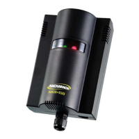
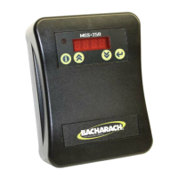
The Bacharach MGS-150 is an instrument for the
connuous monitoring of refrigerant, combusble,
and toxic gases.
The instrument is powered by 12-24V AC or DC
(selectable by an on-board jumper). The output signal
can be selected as either voltage or current. The
on-board relay can be used to switch alarm devices.
P/N: 6309-9002
Revision 0
January 25, 2016
2: SAFETY INSTRUCTIONS
USER MANUAL: Before using this equipment,
carefully read and strictly follow the User Manual
(part number 6309-9000). The user must fully
understand and strictly observe the instrucons.
Use the equipment only for the purposes listed and
under the condions specified in those documents.
CODE COMPLIANCE: Comply with all local and
naonal laws, rules and regulaons associated with
this equipment.
GENUINE PARTS: Use only genuine Bacharach spare
parts and accessories, otherwise proper funconing
of the equipment may be impaired.
TECHNICIAN USE ONLY: This unit must be installed
by a suitably qualified technician who will install this
unit in accordance with these instrucons and the
standards in their parcular industry/country. Opera-
tors of the unit should be aware of the regulaons
and standards in their industry/country for the
operaon of this unit. These notes are only intended
as a guide and the manufacturer bears no responsi-
bility for the installaon or operaon of this unit.
Failure to install and operate the unit in accordance
with these instrucons and with industry guidelines
may cause serious injury including death and the
manufacturer will not be held responsible in this
regard.
SAFE MOUNTING: This monitor must be connected
by a marked, suitably located and easily reached
switch or circuit-breaker as means of disconnecon.
WARNING: Strictly follow the
instrucons in the Gas Detector
Manual (part number 6309-9000)
available at www.MyBacharach.com.
CAUTION: DO NOT MOUNT the
MGS-150 in an area that may
contain flammable liquids or
vapors. Operaon of electrical
equipment in such an area cons-
tutes a safety hazard.
GAS DETECTOR
INSTALLATION GUIDE
3: WEIGHTS AND DIMENSIONS
Type/Enclosure Dimensions Weights
2100 g
ENVIRONMENTAL CONSIDERATIONS: Care-
fully consider the full range of environmental
condions to which the instruments will be
exposed.
TARGET GAS CONSIDERATIONS: The physical
data of the gas or vapor to be detected must
be observed.
APPLICATION CONSIDERATIONS: The specifics
of the applicaon (for example, possible leaks,
air movement/dra, etc.) must be observed.
ACCESSIBILITY CONSIDERATIONS: The degree
of accessibility required for maintenance
purposes must be granted.
ACCESSORY CONSIDERATIONS: The types of
oponal and accessory equipment that will be
used with the system must be kept in mind.
ELECTRONIC CONSIDERATIONS: The system
contains sensive electronic components that
can be easily damaged. Do not touch nor
disturb any of these components.
Mount the MGS-150 according to the above
consideraons, product dimensions (see
Secon 3), maximum wiring lengths (see
Secon 5), and the corresponding mounng
dimensions shown in the illustraons that
follow.
4: MOUNTING
3.39 in (86.0 mm)
2.09 in (53 mm)
1.4 in
(36.00 mm)
1.69 in (43.0 mm)
4.72 in (120 mm)
0.28 in
(7.0 mm)
4.07 in (103.50 mm)
1.0 in
(25.00 mm)
1.0 in
(25.00 mm)
018 in
(4.50 mm)
�
0.18 in
(4.50 mm)
�
0.35 in
(9.0 mm)
�
0.31 in
(8.0 mm)
(146 mm)
(122 mm)
(42 mm)
(59 mm)
(123 mm)
(101 mm)
(144 mm)
M42 thread
4.8 in
5.7 in
5.7 in
2.3 in
1.7 in
4.0 in
mounng slots =
0.35 in (9mm) long x
0.24 in (6mm) wide
Use 3/16-inch screws
(5mm - 6mm )
4.8 in
Thread varies
with model
1”BSP thread
Exd Remote
Head
PRV/IP66
Vent Pipe
Monitoring 1
in BSP Head
Standard
Housing
Ex d Housing
IP66 Housing
Inches
12 x 12 12 x 24 18 x 18 24 x 24 24 round
1 x 1