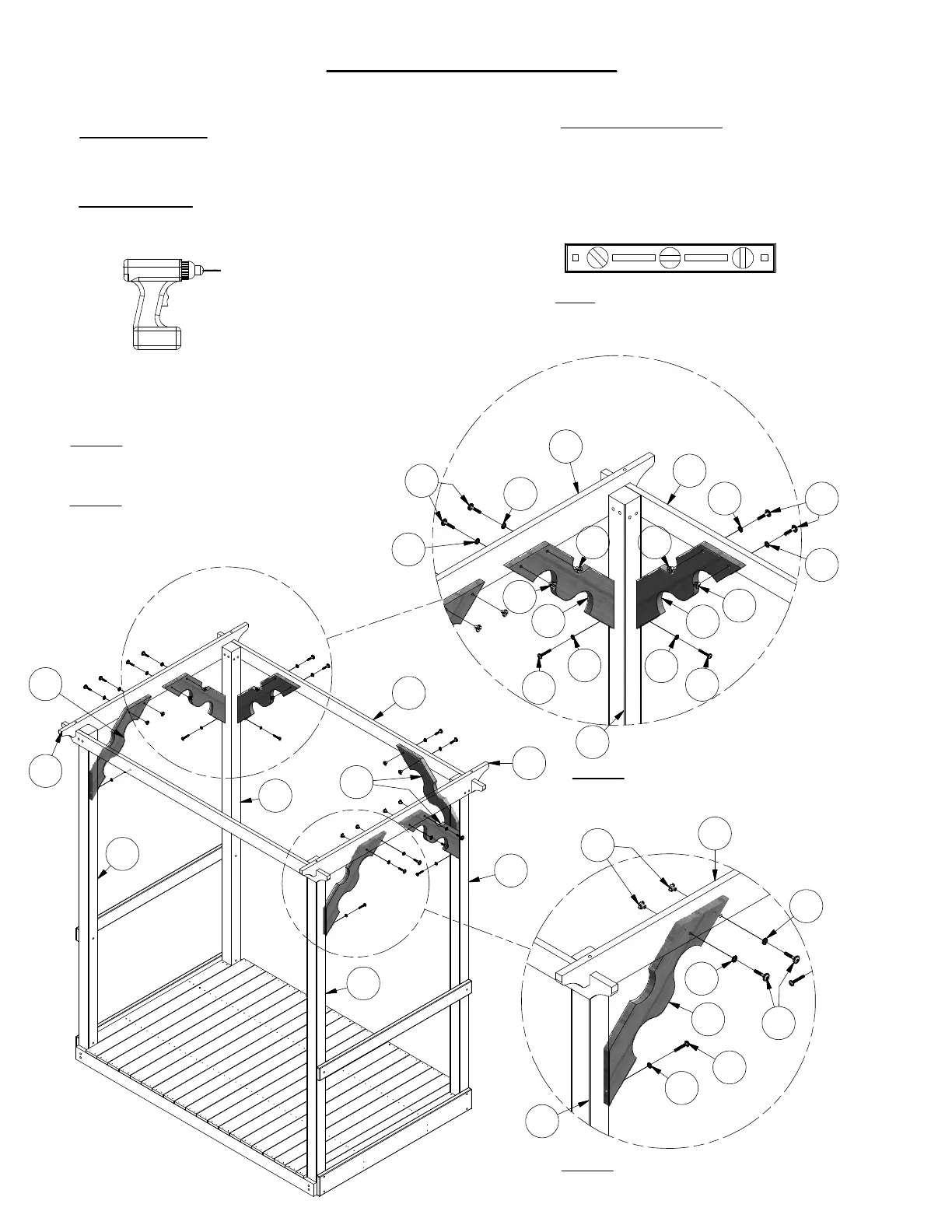
Frame Assembly
Phase 6
Phase Notes
• Assemble with hardware as shown.
Parts needed:
• (6) G4 - CORNER SUPPORT - W101711
Hardware needed:
• (12) J - BOLT WH 5/16x1-3/4 - H100011
• (12) AC - WASHER LOCK EXT 8x19 - H100030
• (12) BG - T-NUT 5/16 - H100074
• (6) LD - LAG SCREW WH 1/4x2 - H100146
• (6) KV - WASHER LOCK EXT 8x15 - H100138
Step 1:
Attach 'G4' Corner Support to
'G3' Pergola Beam using T-Nuts 'BG',
Washers 'AC', and Bolts 'J', as shown.
G3
H2
B1
G4
G4
AC
AC
J
AC
AC
J
BG
BGBG
BG
KV
LD
KV
LD
BG
LD
KV
G4
AC
AC
J
G3
B1
G4
G3
B1
B1
H2
B1
B1
G3
G4
Note: It is vital that the structure
be level before and after each
phase of assembly.
To prevent board splitting, you
must pre-drill each board with
a 1/8" drill bit, before attaching.
Step 2: Attach 'G4' Corner Support to
'B1' Post using Lag Screws 'LD' &
Washers 'KV', as shown. Repeat this
process for the remaining 'G4' Corner
Supports.
Step 3:
Attach 'G4' Corner Support to
'H2' Beam Support using T-Nuts 'BG',
Washers 'AC', and Bolts 'J', as shown.
Step 4:
Attach 'G4' Corner Support to
'G3' Pergola Beam using T-Nuts 'BG',
Washers 'AC', and Bolts 'J', as shown.