HOW TO WIRE
THE PC100
The rear panel of the PC100 controller contains 36 screw
terminals for connecting #28 to #18 gauge insulated wire
(#18 gauge stranded twisted pair shielded cable is recom-
mended.)
A wire stripper and a small screwdriver are the only tools
required. Detailed diagrams in this section illustrate the
proper wiring procedures for all standard and optional
functions.
At installation, be sure to comply with the following
requirements:
• Disconnect power to the unit before attempting any
connection or service to the unit
• Avoid using machine power service for AC power. When
possible, a dedicated or lighting circuit is recommended
• Do not bundle or route signal lines with power lines
• Keep all lines as short as possible
• Use twisted pair shielded wire for all input wiring
• Observe all applicable local electrical codes
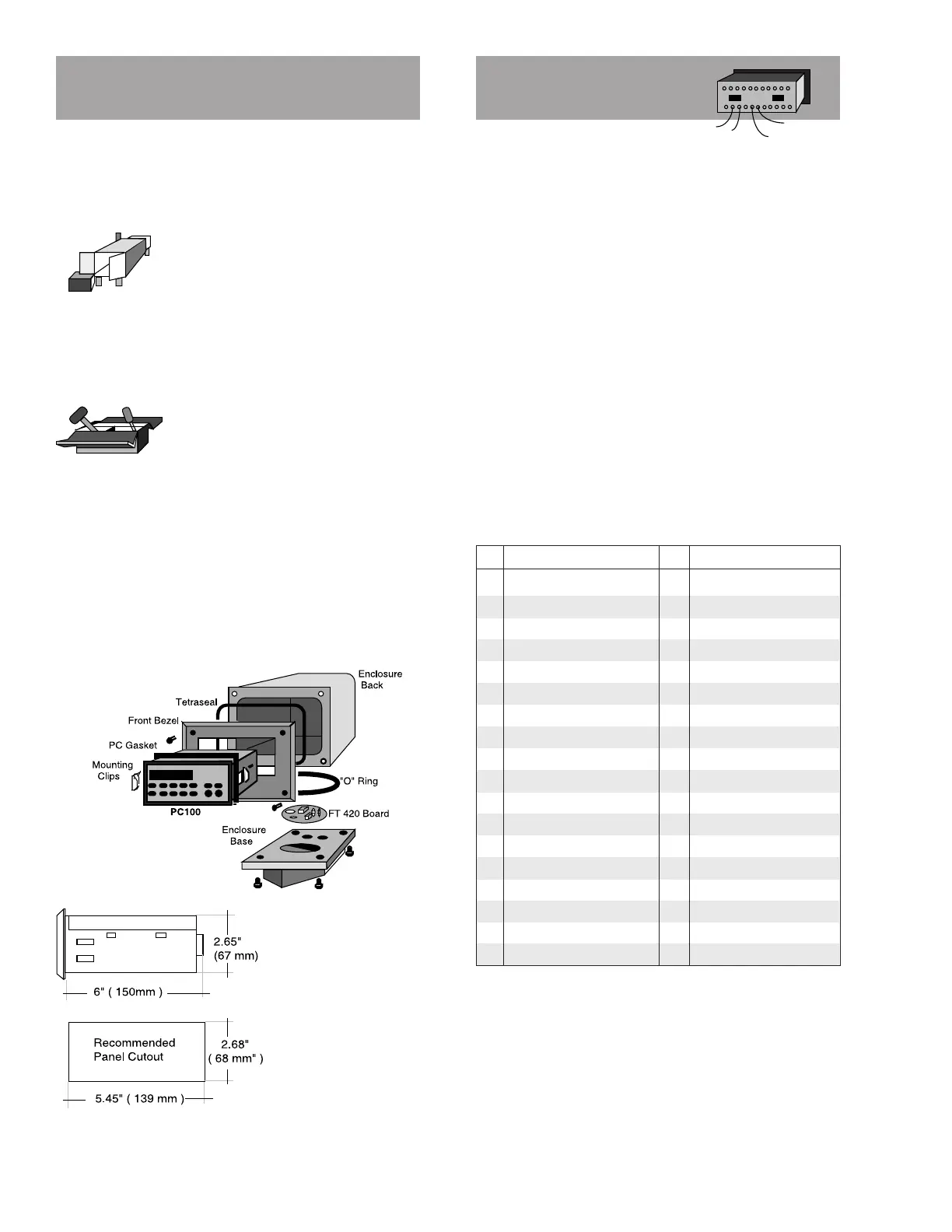
Terminal Identification List
No Function No Function
1 Reset Cycle Counter 19 DC Power Input
2 Resume Remote Input 20 15 VDC Power Output
3 Stop Remote Input 21 DC Common
4 Reset Totalizer 22 Relay K1 Contact NC
5 Transistor Output 1 23 Relay K1 Contact C
6 Transistor Output 2 24 Relay K1 Contact NO
7 Transistor Output 3 25 AC Power Input
8 Transistor Output 1A 26 AC Power Input
9 Transistor Output 2A 27 AC Power Input
10 Transmitter Input 2 28 AC Power Input
11 Low Frequency 2 29 Relay K2 Contact NC
12 DC Common 30 Relay K2 Contact C
13 Low Frequency 1 31 Relay K2 Contact NO
14 Transmitter Input 1 32 Chassis Ground
15 Function Inhibit 33 Serial Data Input (-)
16 Print Command 34 Serial Data Input (+)
17 Start Command 35 Serial Data Output (+)
18 Pulse Input Doubler 36 Serial Data Output(-)
CAUTION: To prevent accidents, power connection should
HOW TO UNPACK, ASSEMBLE
AND INSTALL THE PC100
4
Note: K1 relay coil jumper is factory wired to terminal 8.
K2 relay coil jumper is factory wired to terminal 9. At the
end of the batch, transistor outputs 2 and 2A (terminals 6
and 9) are energized. At prewarn, terminal outputs 1 and 1A
(terminals 5 and 8) are energized.
Note: If damage to the shipping container is obvious,
request that the carrier be present when the product is
unpacked. All claims for equipment damage during transit
are the sole responsibility of the recepient.
UNPACKING
After carefully unpacking the unit, check
for any visible sign of damage. If found,
notify the carrier for insurance purposes
and call the factory for possible replacement. Keep all
packing material in the event that the unit must be return
to the factory.
ASSEMBLY
The PC100 can be installed on the flow-
meter, on a wall or shelf, or in an instru-
mentation panel. The picture below shows
the exploded view of a meter or wall
mounted unit. In this configuration, the
PC100 is shipped separately and must be installed as shown.
(See wiring diagrams for proper transmitter signal connec-
tions.)
The basic unit is equipped for panel mount. To install:
1- Measure and cut mounting hole to the dimensions shown.
2- Install gasket around the mounting bezel.
3- Pass the unit through the front panel cutout.
4- Secure the unit to the panel with the mounting clips.
5- Complete wiring and reassemble unit.
Note: Operating tempera-
ture is 32° F to 130° F (0°
to 55° C) with a maximum
humidity of 85% non-con-
densing.
Always select a mount-
ing location with proper
ventilation and environ-
ment protection.
 Loading...