Do you have a question about the Badger Meter PC100 and is the answer not in the manual?
Covers installation, wiring, operation, and troubleshooting of the PC100.
Lists optional functions and features for the PC100.
Guides for connecting to serial printers or process controllers.
Detailed steps for unpacking, assembling, and installing the PC100 unit.
Lists all terminal connections and their functions for wiring.
Covers wiring requirements, safety precautions, and cable recommendations.
Details the explosion-proof enclosure and identical operation to PC100.
Step-by-step guide for assembling and mounting the PC100XP.
Details on connecting 120 and 240 VAC power supplies to the PC100.
Details on connecting 11-16 VDC power supplies to the PC100.
Guide for connecting Type A reed switch transmitters to the PC100.
Guide for connecting Type B EPT1XP and PEPT1 transmitters.
Instructions for connecting Type C open collector output transmitters.
Instructions for connecting Type D FT420XP transmitters.
Instructions for connecting Type E PFT3 transmitters.
Wiring for single stage valves and main pump motors.
Wiring for two stage valves.
Wiring for feed pumps and high/low flow alarms.
Wiring diagrams for feed pumps and electric pumps.
Details for connecting flow alarms and PC cascade connections.
Wiring for relay pulse, remote totalizer, and batch counter outputs.
Wiring for remote control of unit operations.
Using reset functions and the print input command.
Instructions for wiring a serial printer for data output.
Guide for connecting the PC100 to a process controller.
Information on serial data transmission, ID numbers, and commands.
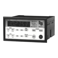
Overview of the PC100 display, indicators, and keypad layout.
How to view data, start, stop, and resume operations.
Steps for programming functions via the front panel keypad.
Details how to program various functions on the PC100.
Highlights essential functions that must be programmed for operation.
Sets how the transmitter input pulses are counted.
Defines counter behavior at batch completion.
Configures the transmitter failure detection timeout.
Sets display decimal points and transistor output functions.
Configures pulse output width and default display mode.
Enables rate mode and calculates the scale factor for units.
Procedure to adjust scale factor for system errors or meter wear.
Allows enabling or disabling of PC100 functions.
Controls for disabling front panel START, STOP, and RESUME commands.
Resets all functions to factory programmed values.
Configures batch size, limits, and autoadjustment for accuracy.
Sets cycle presets, viewing cycle counts, prewarn points, and timeouts.
Enables automatic batch restarts and controls batch initiation.
Configures flow rate display period and high/low setpoints.
Determines how the rate output signal behaves.
Procedures for resetting the totalizer and cycle counters.
Sets serial data mode, baud rate, and unit identifier.
Configures print delays, print events, and data selection for output.
Enables status messages and on-demand printing.
Diagnosing issues with unit power and display functionality.
Resolving problems with transmitter counting and relay de-energization.
Addressing issues with key operation, wear, and display indicators.
Troubleshooting batch programming limits and display errors.
Resolving issues with programming, valve operation, and alarms.
Troubleshooting remote counter issues and totalizer mismatches.
Running the PC100's built-in self-test for diagnostics.
| Category | Controller |
|---|---|
| Enclosure Rating | NEMA 4X |
| Input Voltage | 12-24 VDC |
| Communication Protocol | Modbus RTU |
| Outputs | 2 Relays |
| Inputs | Pulse |