EasyManua.ls Logo

Badger Meter PC200 - User Manual

Badger Meter PC200
36 pages
Print Icon
To Next Page IconTo Next Page
Loading...
Industrial Process Controller
Model PC200
CTL-UM-00483-EN-07 (April 2017)
User Manual

Questions and Answers

  • M
    Michael SandersAug 2, 2025
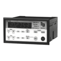
    What to do if the Badger Meter PC200 Controller shows an ALARM?
    • J
      Julie GriffithAug 3, 2025
      When the alarm flag blinks, it indicates an internal alarm. Press SELECT to view the 5-digit error code: * 0001: Data on the display might be corrupted. * 0002: Check programmed values, as the programming cycle might have failed. * 0003: Both error 1 and error 2 have occurred. If the alarm persists, contact your supplier.
  • J
    joanneriggsAug 12, 2025
    Why does my Badger Meter PC200 Controller's flow meter generate too many pulses?
    • K
      kgouldAug 12, 2025
      If the flow meter generates too many pulses, check the following: * Ensure the signal selection is correct. If the sensor is a reed switch, connect it to the low frequency input. * Verify proper grounding of both the PC200 and the flow meter. Refer to "Wiring the PC200" on page 11.
  • B
    Beth SandersAug 22, 2025
    How to troubleshoot a Badger Meter PC200 Controller when the flow meter doesn't generate pulses?
    • C
      Christopher HughesAug 22, 2025
      If the flow meter does not generate pulses, check: * Signal selection: If the sensor generates above 150 Hz, connect it to the high frequency input. * Flow meter, wiring, and terminal connector connections. See “Terminal Connectors” on page 11. * Power supply of the flow meter. See “Voltage Selection Sensor Supply” on page 11.

Summary

Scope of Manual and Safety

Unpacking the PC200

Procedures for safely removing the unit from its packaging.

Safety Considerations and Instructions

General safety guidelines, terminology, symbols, and specific instructions.

PC200 Batch Controller Description

Functions, Inputs, Outputs, and Power

Overview of PC200 features, control interfaces, and power requirements.

Unit Configuration Overview

Configuration of the Unit and Display Information

Details on setting up the PC200 for specific applications and its LCD display.

Installation

Installation Conditions and Mounting

Guidelines for environmental conditions, mounting procedures, and enclosure dimensions.

Wiring the PC200

Sensor Supply Voltage and Terminal Connections

Instructions for sensor supply voltage selection and terminal connector assignments.

Operation

Control Panel and Operator Functions

Overview of the control panel, key functions, and operator interactions.

Operator Alarms

Explanation of alarm types (no-flow, flow rate) and how to clear them.

Configuration and Setup

Programming and Scrolling Setup Levels

How to access, navigate, and change PC200 setup parameters.

Setup Function Details

Comprehensive guide to all setup functions, including presets, alarms, and controls.

Transmitter Pulses Per Unit

Transmitter Pulse Rate Data

Table listing pulses per unit for various compatible transmitters.

Maintenance and Repair

Maintenance Procedures

Guidelines for routine checks, cleaning, and general upkeep of the unit.

Technical Specifications

Hardware, Environmental, and Power Specs

Details on display, enclosure, environment, power, terminals, and EMC.

Control, Input, Output, and Flow Rate Specs

Specifications for control inputs/outputs, operator functions, and flow rate parameters.

Troubleshooting

Troubleshooting Common Issues

Solutions for problems like no pulses, too many pulses, and alarm codes.

Record of Configuration Settings

Configuration Settings Log

A template to log PC200 configuration settings and parameters.

Badger Meter PC200 Specifications

General IconGeneral
BrandBadger Meter
ModelPC200
CategoryController
LanguageEnglish

Related product manuals