WIRING THE PC200
At installation, be sure to comply with the following requirements:
• Disconnect power to the unit before attempting any connection or service to the unit.
• Avoid using machine power service for AC power. When possible, use a dedicated or lighting circuit.
• Do not bundle or route signal lines with power lines.
• Keep all lines as short as possible.
• Use shielded wire for all input wiring.
• Observe all local electrical codes.
TO PREVENT ACCIDENTS, POWER SHOULD NOT BE APPLIED UNTIL ALL OTHER CONNECTIONS HAVE BEEN COMPLETED.
Voltage Selection Sensor Supply
Sensor supply
8.2…12 or 24V DC
A power supply for the sensor is available. The flow meter can be powered with 8.2, 12 or 24V DC.
Total power consumption
Max. 50 mA @ 24V
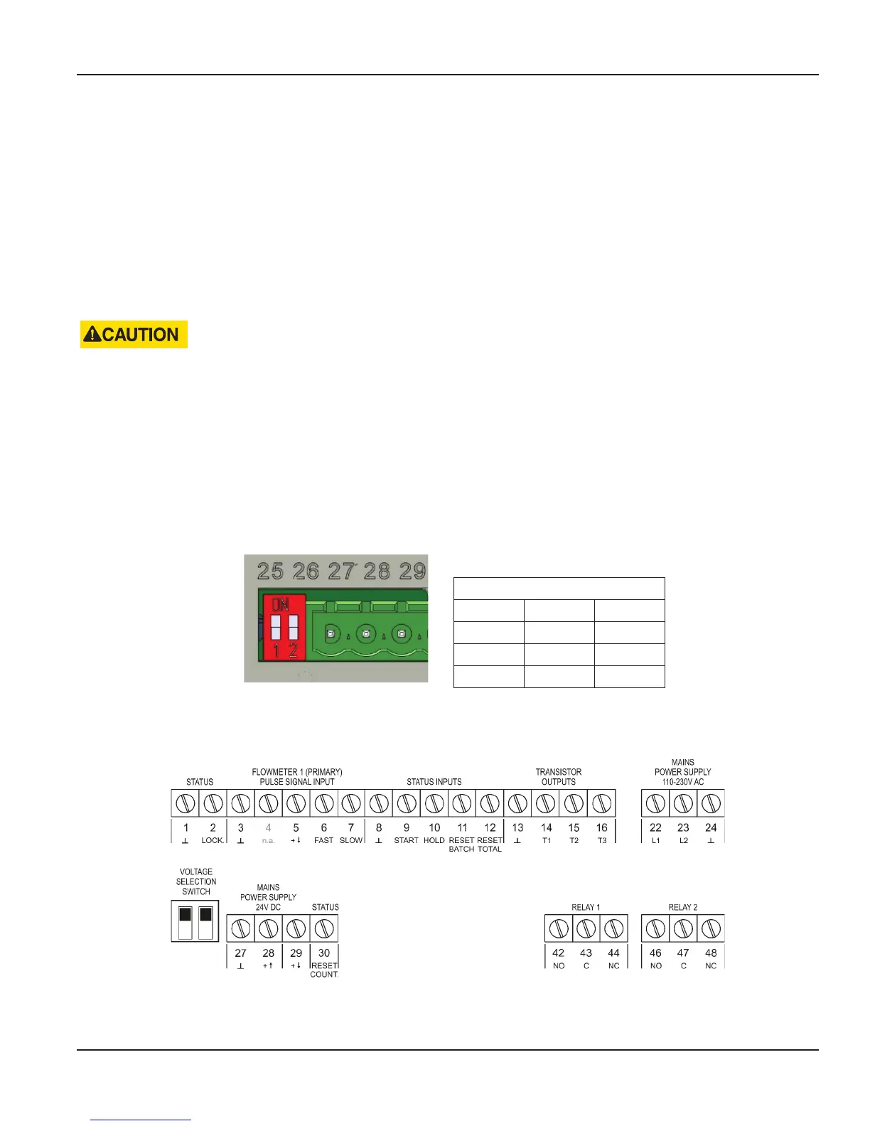
The voltage is selected with the two switches at the rear of the enclosure.
Figure 5: Switch setting sensor supply voltage
Switch positions
Voltage Selection
Switch 1 Switch 2 Voltage
on on 24V DC
on off 8.2V DC
off off 12V DC
Table 1: Switch positions
Terminal Connectors
Figure 6: Overview of terminal connectors
User Manual
Page 11 April 2017 CTL-UM-00483-EN-07