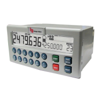
PC200 BATCH CONTROLLER DESCRIPTION
Functions and Features
The batch controller model PC200 is a microprocessor-driven instrument designed for batching and filling both small and
large quantities, as well as displaying total, accumulated total and flow rate.
This product is designed with a focus on:
• Ease-of-use with the numerical keyboard.
• Ruggedness for its application with a robust enclosure, keyboard and proper mechanical relays.
• Clear operator information: all relevant data can be monitored in one glance.
• User-friendly installation with quality plug-and-play terminals; suitable for both AC and DC applications (standard).
• A wide range of inputs, outputs and functions for a broad fulfillment in many applications.
Flow Meter Input
One flow meter: a passive or active pulse signal output can be connected to the PC200. The input circuit supports low and
high frequency flow meters. A power supply is available to power the sensor with 8 / 12 or 24V DC.
Control Inputs
The PC200 has six control inputs:
• Start
• Hold
• Resume
• Reset totalizer
• Reset cycle counter
• Lockout the entire keyboard
Control Outputs
The PC200 has five control outputs—two mechanical relay outputs and three transistor outputs. The two mechanical relay
outputs (make and break) are used for batching with two-stage control or one-stage control. Three transistor outputs are for
connection to PLCs or other controlling equipment. The function of relay R2 and the transistor outputs can be configured to:
• Batching
• Two-stage control
• High flow rate alarm
• Low flow rate alarm
• No-flow alarm
• Any alarm
• Scaled pulse output
• Pre-warn or end of batch signal
Power Supply
AC power supply: as standard, the PC200 will operate on 110…230V AC.
DC power supply: as standard, the PC200 can also operate on 24V DC.
User Manual
Page 7 April 2017 CTL-UM-00483-EN-07

 Loading...