EasyManua.ls Logo

Bailey Infi90 - Page 38

Default Icon
68 pages
Print Icon
To Next Page IconTo Next Page
To Previous Page IconTo Previous Page
Loading...
E96
506A
INSTALLATION
~
POST0NA
'0~
EWBLNC +24Y
MmHOR
Pt
S
Tf"lt~
8
F(P
+tN
+;·W
+
~v
.&::
l'SV
M
JtHORN~
J1
P>~
1
rt~
A
f(!R
":)/A~
AN0
FOR
EPASO
\
P:J<~IT
1N
B fOR
2~0
VA:
I
OBOADD~
,a
()
,;:
0
,-
l
~
~
0 Do 0 D
(
-
-
n
0
0
~
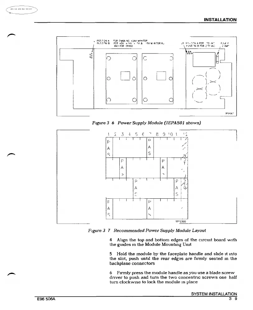
Figure
3 6
Power
Supply
Module
(I
EPA
SO
1
shown)
~
3
s
E c
Cl
1Q
1
1
~
p
D
I I
/I
A
A
<l
c;
s
}~-!
p p
:;,
Tj
A
A
I
D
p
s
A
A
(6;
s
"
1:
p
A
lc
1)
'-,
lP"OJOO
Figure
3 7
Recommended
Power
Supply
Module
Layout
4
Ahgn
the
top
and
bottom
edges
of
the
c1rcmt
board
w1th
the
gmdes
m
the
Module
Mountmg
Umt
5
Hold
the
module
by
the
faceplate
handle
and
sbde
1t
mto
the
slot,
push
unttl
the
rear
edges
are
firmly
seated
m
the
backplane
connectors
6
Ftnnly
press
the
module
handle
as
you
use
a
blade
screw
dnver
to
push
and
tum
the
two
concentnc
screws
one
half
tum
clockwtse
to
lock
the
module
m
place
SYSTEM INSTALLATION
3 9
Artisan Technology Group - Quality Instrumentation ... Guaranteed | (888) 88-SOURCE | www.artisantg.com

Other manuals for Bailey Infi90