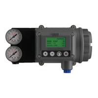
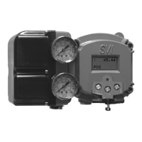
The Masoneilan 4700E/4800E Electropneumatic Positioner is a force-balanced device with an integrated 4000 I/P Converter, designed to control the position of a control valve's plug in response to a 4-20 mA control signal. Feedback on the valve's position is obtained via a cam mechanism. The 4800E model specifically features a high-flow pneumatic block, offering enhanced performance for applications requiring greater pneumatic capacity.
Function Description:
The positioner acts as an interface between an electrical control signal and a pneumatic valve actuator. It receives a 4-20 mA current signal, converts it into a proportional pneumatic output pressure, and applies this pressure to the valve actuator to achieve the desired valve plug position. The force-balanced principle ensures accurate and stable control, while the integrated I/P converter simplifies the overall control loop.
Important Technical Specifications:
- Input Signal: 4-20 mA, self-powered.
- Input Impedance: 170 ohms.
- Maximum Power:
- Flameproof atmosphere: 0.8 W
- Intrinsic Safety atmosphere: 1.1 W (T4) or 0.33 W (T6)
- Pneumatic Supply Pressure: Must match the serial plate specification, not exceeding 700 kPa (100 psi). Intended for use with industrial compressed air or natural gas systems (Zone 0 or Div 1 for natural gas).
- Tubing Diameter (Minimum):
- 4700E: 4 x 6 mm
- 4800E: 10 x 12 mm
- Performance (% of signal range):
- Dead Zone: < 0.5% (4700E), < 0.5% (4800E)
- Hysteresis: < 0.5% (4700E), < 0.8% (4800E)
- Repeatability: 0.5% (4700E), 0.5% (4800E)
- Sensitivity: 0.3% (4700E), 0.5% (4800E)
- Conformity: ± 1% (4700E), ± 1% (4800E)
- Service Temperature Range: -40°C to +85°C (-40°F to +185°F) (standard instrument). Refer to apparatus marking for specific limits.
- Storage Temperature: -55°C to +90°C (-67°F to +194°F).
- Electrical Protection Index: IP 66 (housing).
- ATEX Markings:
- Intrinsic Safety (ia): II 1GD, Ex ia h IIC T6 Ga (Tamb.= -40°C to +55°C, Pi= 0.33 W), Ex ia h IIC T4 Ga (Tamb.= -40°C to +80°C, Pi= 1.1 W), Ex ia h IIIC Da T90°C (Tamb.= -40°C to +80°C, Pi= 1.1 W).
- Flameproof (db) / Dust Ignition Protection (tb): II 2GD, Ex db h IIC T6 Gb (Tamb.= -40°C to +55°C), Ex db h IIC T5 Gb (Tamb.= -40°C to +70°C), Ex db h IIC T4 Gb (Tamb.= -40°C to +85°C), Ex tb IIIC T90°C Db (Tamb.= -40°C to +55°C).
- Intrinsic Safety Entity Parameters (Model 4000 I/P Converter):
- Ui (Max. Input Voltage): 30 V
- Ii (Max. Input Current): 110 mA
- Pi (Max. Input Power): 1100 mW (T4), 0.33 mW (T6)
- Ci (Max. Internal Capacitance): 0 nF
- Li (Max. Internal Inductivity): 0 µH
Usage Features:
- Explosive Atmosphere Compliance: These instruments comply with European Directive ATEX 2014/34/EU and EMC 2014/30/EU, certified for use in Gas or Dust explosive atmospheres (Groups IIC or IIIC).
- Installation Flexibility: Can be installed in various hazardous zones depending on the protection mode (zones 0, 1, 2, 20, 21, 22 for "ia"; zones 1, 2, 21, 22 for "db" and "tb").
- Conduit Entry Options: Connections can be made using certified Ex d IIC / Ex tD A21 or Ex t IIIC Db cable entries directly on the 1/2" NPT (ANSI/ASME B1.20.1) housing conduit connection or M20 (ISO965-1 & ISO965-3). Adaptors or reducers may be used if ATEX or IECEx certified.
- Self-Powered: The positioner operates as a self-powered 4-20mA current receiver, simplifying electrical wiring.
- Calibration: The positioner is factory calibrated when supplied mounted on a valve. If supplied alone, calibration involves adjusting the zero (using nut 4b) and span (using spring 5) to ensure the valve's full stroke corresponds to the control signal range. The Model 4000 I/P Converter does not require adjustment.
- Safety Features: Includes a cover (C) with a seal (J) and a safety screw (V) that must be tightened before switching on or after any work to maintain explosion protection.
Maintenance Features:
- General Rules: All maintenance operations must comply with EN/IEC 60079-17 and/or national/local regulations for explosive atmospheres.
- Pre-Maintenance Checks: Before any work, ensure local conditions in the hazardous area permit safe opening of the cover. Power off the instrument.
- During Maintenance:
- Inspect for damage and replace defective parts with genuine manufacturer replacements only.
- Check the condition of the main cover seal (C) and the housing.
- Inspect the cable gland and electrical connections.
- Pilot Maintenance: Disconnect air supply, remove the pilot from the pneumatic block, clean parts, blow air through ports and tubing, and reassemble using three new O-rings.
- I/P Module Replacement: Check and replace the three O-rings (22, 23, 24) if necessary.
- Cleaning: Clean the enclosure to prevent dust accumulation, especially for instruments in zones 20, 21, and 22. Avoid aggressive substances that could damage metallic or plastic parts. For cleaning in hazardous areas, use a damp cloth and ensure the area is free of explosive atmosphere.
- Post-Maintenance Checks: After any work, ensure the cover (C) is fully screwed and the security cover screw (V) is well locked.
- Annual Gasket Check: It is the user's responsibility to check the gasket annually and replace defective parts with manufacturer's replacements if damaged.
- Electrostatic Charging Hazard: Non-metallic parts/labels should be cleaned with a damp cloth in a non-hazardous area to avoid electrostatic sparks.
- Temperature Considerations: Users must verify that the temperature increase from mechanical parts or process thermal radiation does not exceed the allowed temperature classification, in accordance with EN/IEC 60079-14.
- Intrinsic Safety Installation: Cable entry must have at least IP54 protection. For aluminum housing in Group II Category 1 (Zone 0), consider potential ignition from impact/friction sparks. The current source supply must be certified for IIC and intrinsic safety loop approved, with entity parameters compatible with the Model 4000 I/P Converter.
- Flameproof Installation: For ambient temperatures >70°C, select a cable entry and cable compatible with the higher temperature (75°C for 70°C ambient, 90°C for 85°C ambient). Cable entry and cable must be compatible with a minimum temperature of -40°C. Cable entry must have at least IP66/67 protection.
- I/P Converter Orientation: If the Model 4000 I/P Converter is mounted with the plastic baffle axis in the vertical position with the baffle uppermost, the ingress protection against water is invalidated. This orientation is only permissible if the location provides protection against falling water.