WATER FLOW
THREE RULES OF WATER FLOW
FOR THE CLIM8ZONE
TM
UNIT
1
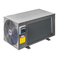
The CLIM8ZONE
TM
unit (figure xx, A) should have an input water flow of 11.9 US
GPM (45 LPM) +/- 10% for optimal eiciency when heating or cooling the water.
2
The water flow into the CLIM8ZONE
TM
unit should be greater than 3.57 US GPM
(13.5 LPM) to prevent a low flow error.
3
The water flow into the CLIM8ZONE
TM
unit should be less than 17.8 US GPM to
ensure the unit is not damaged over extended use.
Water flow rate for the BP Control System:
Minimum: 23 GPM (5.22 m3/H)
The BP Control System has a minimum specified flow
rate of water through the electric heater for the BP
Control System to function properly. Therefore, a bypass
plumbing setup with slice values must be used in the hot
tub to allow for both the flow rate requirements of the
CLIM8ZONE
TM
unit and the flow rate requirements of
the BP Control System heater to be met in the hot tub.
The installer shall adjust the water flow into the
CLIM8ZONE
TM
unit by using the ball valve to ensure that
the flow rate is within the recommended ranges.
Low or No Flow Condition
The CLIM8ZONE
TM
unit will shut itself o for safety
reasons anytime the sensed water flow through the Heat
Pump falls below a threshold of 3.6 GPM (0.81 m3/h).
During a Low/No Flow condition, the CLIM8ZONE
TM
unit will not heat or cool the water and will display an
error message on the control panel display.
High Temperature Safety Protection
The CLIM8ZONE
TM
unit will shut o all heating
or cooling for safety reasons anytime the water
temperature exceeds 43°C/109.4°F for 5 seconds at the
outlet or inlet.
Ozone / UV
Make sure any ozone / UV units are installed down
stream from the CLIM8ZONE
TM
unit (Figure 9, F).
CLIM8ZONE
TM
Water Flow Rates US Gallons Per Minute Liter Per Minute Meter
3
/Hour
Optimal flow rate for heating/cooling 11.89 45.0 2.70
Maximum flow rate for heating/cooling (+10%) 13.08 49.5 2.97
Minimum flow rate for heating/cooling (-10%) 10.70 40.5 2.43
Maximum flow rate to prevent damage 17.83 67.5 4.05
Minimum flow rate to prevent low flow error 3.57 13.5 0.81
General Pump Type HIGH Speed Amps LOW Speed Amps
Flow Control Valve
with 1.5" Plumbing
Flow Control Valve
with 2" Plumbing
Flow Control Valve
with 2.5" Plumbing
1.05A CIRC 60Hz 1.05 73002 73003 NO
1.00A CIRC 60Hz 1.00 73002 73003 NO
0.63A CIRC 60Hz 0.63 NO 73003 NO
16/4 56 Frame 60Hz 16.4 4.8 NO 73002 73002
16/4 56 Frame "Circ Killer" 60Hz 14 1.1 73002 73003 NO
12/2 56 Frame 60Hz 12.1 2.0 NO 73002 73002
12/4.4 56 Frame 60Hz 12 4.4 NO 73002 73002
12/3.5 "XL" with Larger Impeller 60Hz 12 3.5 NO 73002 73002
12/1 56 Frame "Circ Killer" 60Hz 12 1.0 73002 73003 NO
10/3 48 Frame 60Hz 10.7 3.0 NO 73002 73002
8.8/3 48 Frame 60Hz 8.8 3.0 73002 73002 NO
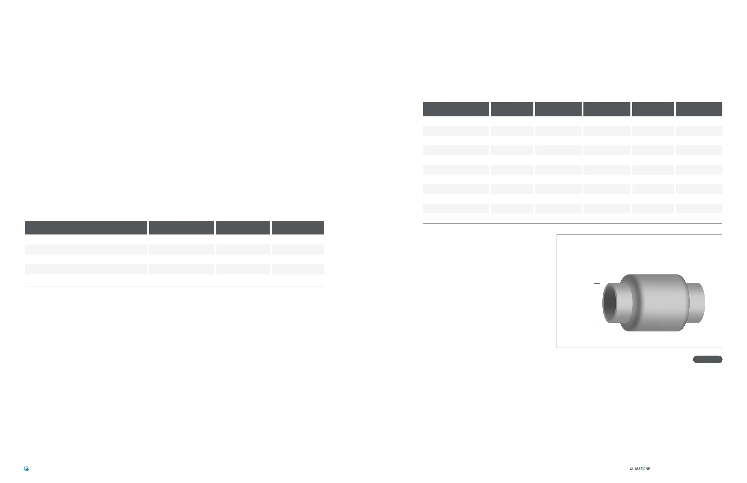
73002: Flow Control Valve, High Amp
73003: Flow Control Valve, Low Amp
NO: Cannot use this pump
2.0"
FLOW CONTROL VALVE OPTIONS
HEATING PUMP & FLOW CONTROL VALVE
CONFIGURATION CHART
Part number: 73002, High Amp (Patent Pending)
Part number: 73003, Low Amp (Patent Pending)
Patent Pending
TM
INSTALLATION GUIDE 42391 Rev A
Balboa Water Group | Your Single Source Solution
23
22
Figure 10