Follow these steps to make the
electrical connections:
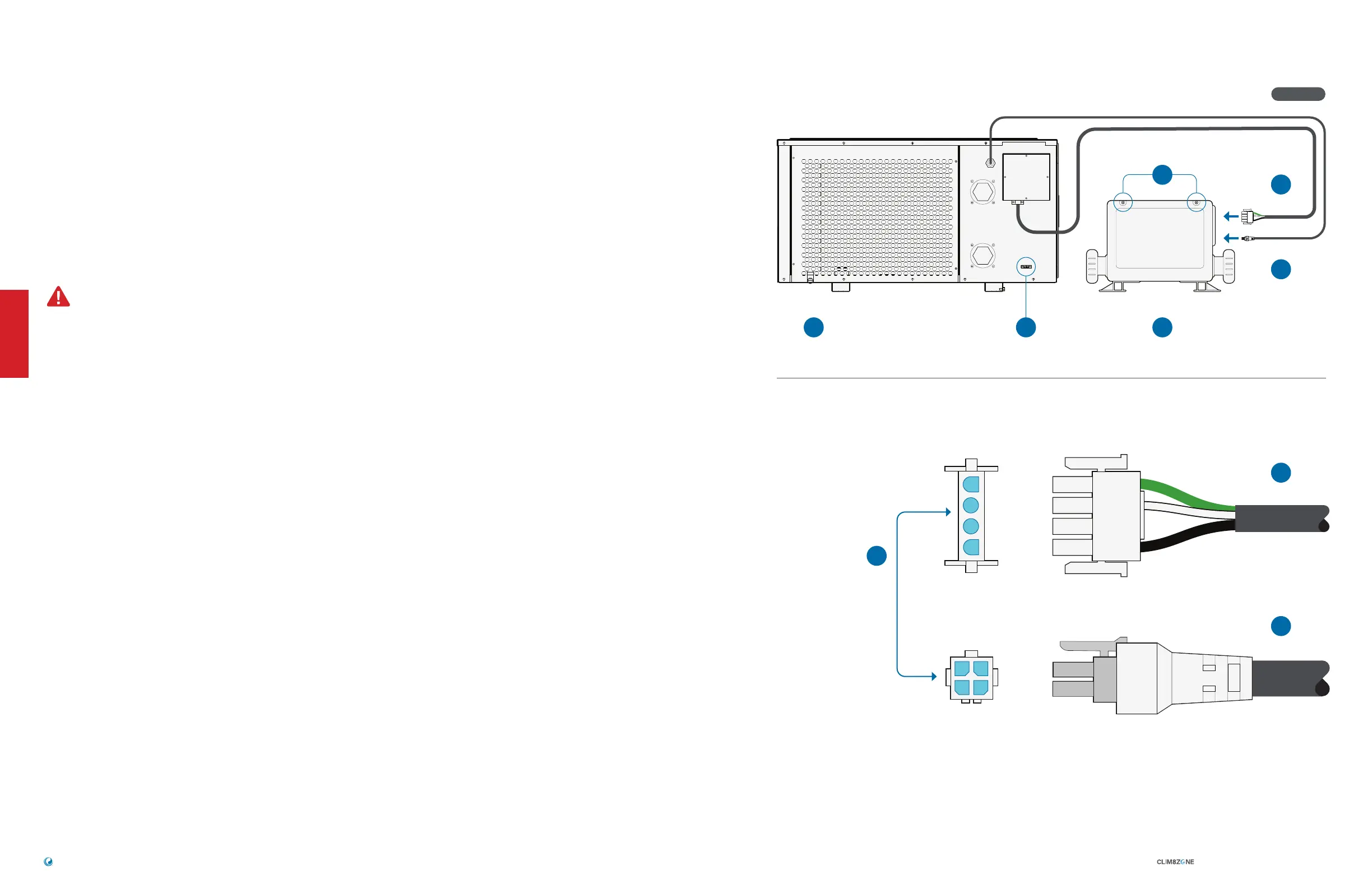
1 - Make sure the BP Control System (figure 6, B) is
powered O at the GFCI or circuit breaker before
starting the installation process.
2 - Remove the lid from the BP Control System
(figure 6, B) by loosening these two screws (figure 6, C)
with a Phillips head screwdriver.
There is a wiring diagram in the inside surface of the lid.
Refer to the wiring diagram during steps 3 and 4.
3 - Connect the power cord (figure 6, D) to the circuit
board of the BP Control System (figure 6, B). Refer
to the wiring diagram for the proper connection. The
connectors are keyed, so make sure they are properly
aligned (figure 6, F) before making the connection.
4 - Connect the data bus (figure 6, E) to the circuit board
of the BP Control System (figure 6, B). Refer to the wiring
diagram for the proper connection. The connectors are
keyed, so make sure they are properly aligned
(figure 6, F) before making the connection.
5 - Reinstall the lid of the BP Control System
(figure 6, B).
6 - Bonding: This unit is provided with a grounding lug
(figure 6, G) and must be electrically bonded to the spa
common bonding grid.
Connect the grounding lug with the spa common
bonding grid with a #8 minimum solid copper wire.
7 - Power On the BP Control System at the GFCI or
circuit breaker.
WARNING
There are no user serviceable parts inside of
the CLIM8ZONE
TM
unit or the control system. All
connections must be made by a qualified electrician in
accordance with the country or local electrical codes in
eect at the time of installation.
IMPORTANT
◆ Earthing is required for protection against
short-circuits inside the unit. Always provide a good
earth connection.
◆ Before connecting the unit, verify that the supply
voltage matches the required voltage of the heat pump.
◆ It is recommended to connect the heat pump to a
circuit with its own fuse or circuit breaker.
CLIMZONE
TM
MAXIMUM CURRENT:
220-240 VAC
50-60 Hz
5.71 A
ELECTRICAL
CONNECTIONS
NORTH AMERICA
TM
INSTALLATION GUIDE 42391 Rev A
Balboa Water Group | Your Single Source Solution
15
14
D
Power Cord
Data Bus
E
BP Control System
B
CLIM8ZONE
TM
Unit
A
C
D
Power Cord
Data Bus
E
Female connector
The connectors
are keyed to help
insure proper
connections.
Male Connector
Female connector Male Connector
F
Figure 6
G
BONDING LUGS