6 WIRING INSTRUCTIONS
WARNING! Read Safety Warning, on page 6, before using this control. Disconnect the main power
when making connections to the control.
Important Application Note: To avoid erratic operation, do not bundle the AC line and motor wires with
wires from signal following, start/stop contacts, or any other signal wires. Also, do not bundle motor
wires from multiple controls in the same conduit. Use shielded cables on all signal wiring over 12” (30
cm). The shield should be earth grounded on the control side only. Wire the control in accordance with
the National Electrical Code requirements and other local codes that may apply.
13
6.1 AC Line Connection – Wire the AC line to Terminals “L1” (Line Fuse) and “L2”, as shown in Figure 1, on
page 10. If one of the AC line inputs is a neutral (N), wire it to Terminal “L2”.
CAUTION! The rated AC line voltage (115, 208/230) of the control must match the actual AC line
input voltage. See Section 7.1, on page 19.
Catalog No. BC141 operates on 115 Volt AC line input only. Catalog No. BC142 operates on 208/230 Volt
AC line input only. Catalog BC142-6 operates on 115 Volt AC line input when Jumper J1 is set to the “115”
position and operates on 208/230 Volt AC line input when Jumper J1 is set to the “230V” position (factory
setting).
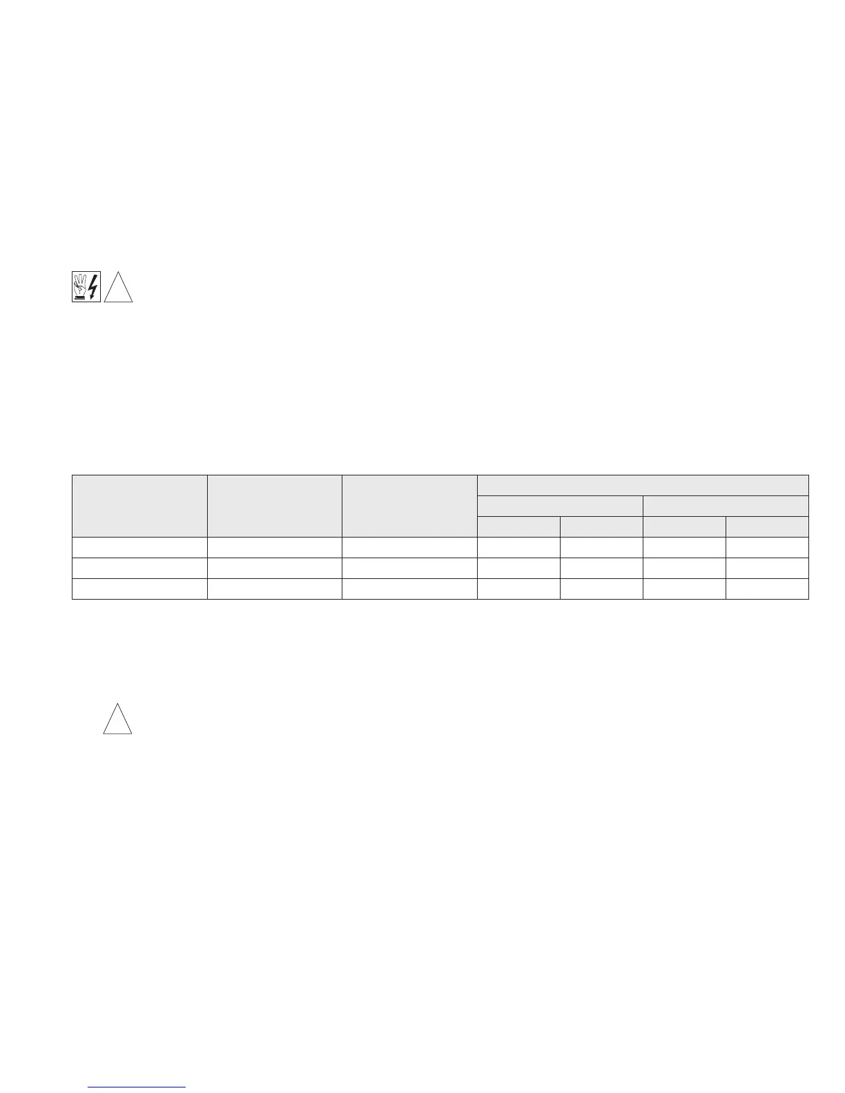
Maximum Motor Current
(Amps DC)
90 - 130 Volt DC Motors
(Maximum HP)
180 Volt DC Motors
(Maximum HP)
Minimum Wire Size (Cu)
Maximum 50 Ft. Maximum 100 Ft.
AWG
mm
2
AWG
mm
2
6 .5 1 16 1.3 14 2.1
12 1 2 14 2.1 12* 3.3*
16 1.5 3 12* 3.3* 12* 3.3*
TABLE 3 – MINIMUM SUPPLY WIRE SIZE REQUIREMENTS
* Maximum recommended wire size.