www.balluff.com 2english
BTL BNC_ 00- _ _ _ _ -C12NL_ _0-000S04 / BTL ZNC_ 00- _ _ _ _ -C12NL_ _0-000S04
Magnetostrictive Linear Position Sensor – Rod Style
953559_AA ∙ EN ∙ E22; subject to modification.
Installation
For examples and further information on
installation, see the user’s guide.
Suitable nuts for the mounting thread are
available as accessories.
We recommend using non-magnetizable material to mount
the BTL and magnet.
If using magnetizable material, the BTL must be protected
against magnetic interference through suitable measures
(e.g. spacer ring made of non-magnetizable material, a
suitable distance from strong external magnetic fields).
If installed in a hydraulic cylinder, the magnet should not
make contact with the rod. Minimum bore diameter in the
support piston:
Rod diameter Bore diameter D2
10.2mm At least 13mm
NOTICE
Interference in function
Improper installation can compromise the function of the
BTL and result in increased wear.
► Ensure that the contact surface of the BTL is in full
contact with the mounting surface.
► Seal the hole perfectly (O-ring/flat seal).
Mounting in a hole with internal thread (mounting
hole)
Depending on the version, the BTL comes with an
M18×1.5 thread (according to ISO) or a 3/4“-16UNF
thread (according to SAE) to secure it.
1. Make a mounting hole with thread (possibly with
countersink for the O-ring).
2. Screw the BTL with mounting thread into the mounting
hole (max. torque75Nm).
Mounting in a through-hole
1. Guide the BTL through the hole.
2. Screw the mounting nut (max. torque75Nm) onto the
mounting thread on the rod side.
Further steps
► Install the magnet (accessory).
► From measuring length of 500mm: Support the rod
and if necessary screw on at the end.
Cable routing
Defined ground!
The BTL and the control cabinet must be at the
same ground potential.
Magnetic fields
The position measuring system is a magnetostrictive
system. Ensure that there is sufficient distance between
the BTL and the transducer/holding cylinder and strong,
external magnetic fields.
Cable routing
All cables between BTL, control and power supply must
be routed tension-free. In order to avoid electromagnetic
interference, ensure sufficient distance to cables carrying a
heavy current and cables with high-frequency voltage
signals (e.g. of frequency converters).
Cable length
For IO-Link operation, the maximum cable length is 20m.
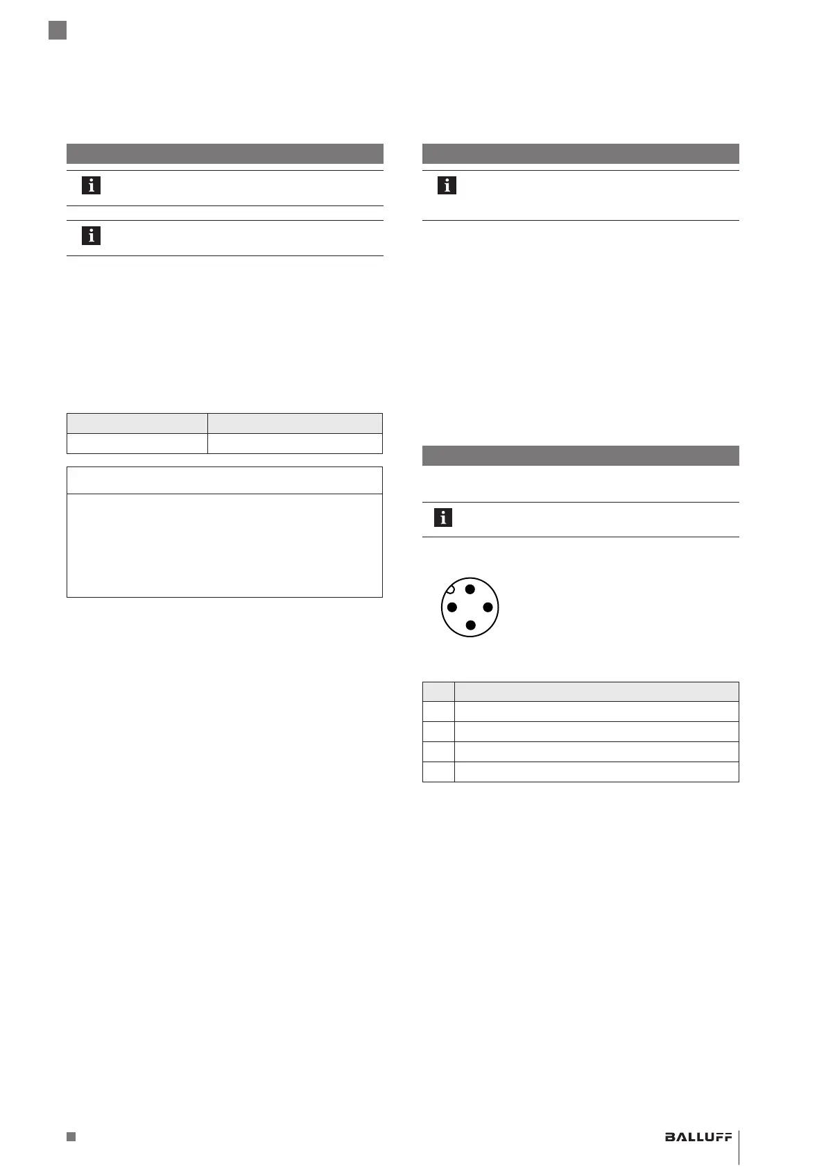
Electrical Connection
The electrical connection is made using a connector.
See the information about cable routing.
4
3
1
2
Pin assignment ofS04 (view from
above on BTL)
Pin Signal
1 L+ (18…30V)
2 Not assigned
1)
3 L− (GND)
4 C/Q (IO-Link communication)
1)
Non-assigned wires can be connected to GND on the control side.
 Loading...


