www.balluff.com 9english
4
Product description (continued)
4.2 Function
To determine the position of a plant component, a magnet
is connected to the component. Together they are moved
along a waveguide located inside the BTL.
An internally generated INIT pulse interacts with the
magnetic field of the magnet to generate a torsional wave
in the waveguide which propagates at ultrasonic velocity.
The component of the torsional wave which arrives at the
end of the waveguide is absorbed in the damping zone to
prevent reflection. The component of the torsional wave
which arrives at the beginning of the waveguide is
converted by a coil into an electrical signal. The position of
the magnet and thus at the same time that of the plant
component is determined from the running time of the
shaft.
Depending on the version, the position is output as a
voltage or current value with rising or falling gradient.
Up to 2 magnets can be used for FMM (Flexible Magnet
Mode).
The following functions can be selected for the output
values:
– Position
– Velocity
– Position difference
The entire range of functions can only be
configured with the PC software Balluff
EnginEEring Tool (BET). For this, the IO-Link
master must be connected. Communication is
realized via IO-Link.
4.3 Display elements
Signal Meaning
Green Normal function
Magnet is within the measuring range.
Yellow
flashing, 3Hz
Warning
Magnet is outside the measuring range.
Red flashing,
1Hz
Measurement error
No magnet
Red flashing,
3Hz
Output error
1)
Short-circuit at voltage output or
interruption on current output.
1)
Is only displayed for versions with 2 current outputs if the error is present
at the same time at both outputs.
Tab. 4-1: LED display
With 1magnet and 2 outputs the priority of the LED
display is as follows (highest to lowest priority):
– Output error
– Measurement error
– Warning
– Normal function
For FMM (Flexible Magnet Mode) with 1magnet the LED
display relates to output 1 (output 2 issues the error value
continuously).
For FMM (Flexible Magnet Mode) with 2magnets the LED
display shows the status with the highest priority of both
outputs.
More than 2 magnets are ignored.
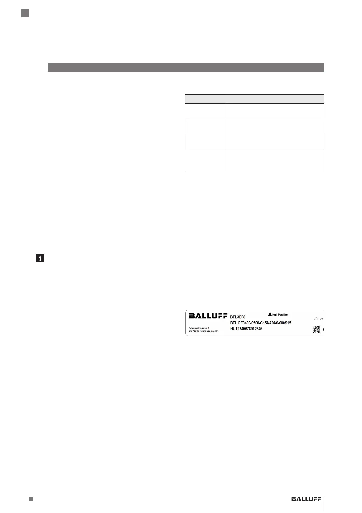
4.4 Part label
2)
3)
4)
4)
2)
Order code
3)
Type
4)
Serial number
Fig. 4-2: Part label (section, example)
BTL PF _ 400- _ _ _ _ -C15A _ _ _ _ - _ _ _ _ _ _
Magnetostrictive Linear Position Sensor – Profile Style
 Loading...


