www.balluff.com 3english
BTL PF _ 400- _ _ _ _ -C15A _ _ _ _ -000S35
Magnetostrictive Linear Position Sensor – Profile Style
955203_AA ∙ EN ∙ E22; subject to modification.
Shielding and cable routing
Defined ground!
The BTL and the control cabinet must be at the
same ground potential.
Shielding
Observe the following instructions to ensure
electromagnetic compatibility (EMC):
– Connect BTL and controller using a shielded cable.
Shielding: Braided copper shield with minimum 85%
coverage.
– Shield is internally connected to connector housing.
Magnetic fields
The position measuring system is a magnetostrictive
system. Ensure that there is sufficient distance between
the BTL and the transducer/holding cylinder and strong,
external magnetic fields.
Cable routing
All cables between BTL, control and power supply must
be routed tension-free. In order to avoid electromagnetic
interference, ensure sufficient distance to cables carrying a
heavy current and cables with high-frequency voltage
signals (e.g. of frequency converters).
Cable length
BTL …-C15AA/A1… Max. 30 m
1)
BTL …-C15AE/A5/AC/A3… Max. 100 m
1)
1)
Prerequisite: Construction, shielding and routing preclude the effect of
any external noise fields.
Display elements
Signal Meaning
Green Normal function
Yellow flashing,
3Hz
Warning
Magnet is outside the measuring
range.
Red flashing, 1Hz Measurement error
No magnet
Red flashing, 3Hz Output error
1)
Short-circuit at voltage output or
interruption on current output.
1)
Is only displayed for versions with 2 current outputs if the error is
present at the same time at both outputs.
With 1magnet and 2 outputs the priority of the LED
display is as follows (highest to lowest priority):
Output error, measurement error, Warning, ormal function
For FMM (Flexible Magnet Mode) with 1magnet the LED
display relates to output 1 (output 2 issues the error value
continuously).
For FMM (Flexible Magnet Mode) with 2magnets the LED
display shows the status with the highest priority of both
outputs.
More than 2 magnets are ignored.
Installation (continued)
The magnetostrictive linear position sensor is electrically
isolated from the machine with the supplied insulating
bushes.
1. Guide the BTL into the mounting clamps.
2. Attach the BTL to the base using mounting screws
(tighten screws in the clamps with max.2Nm).
3. Install the magnet (accessory).
The magnetostrictive linear position sensor in
profile housing is suitable both for floating, i.e.
non-contacting magnets and for captive
magnets (see images).
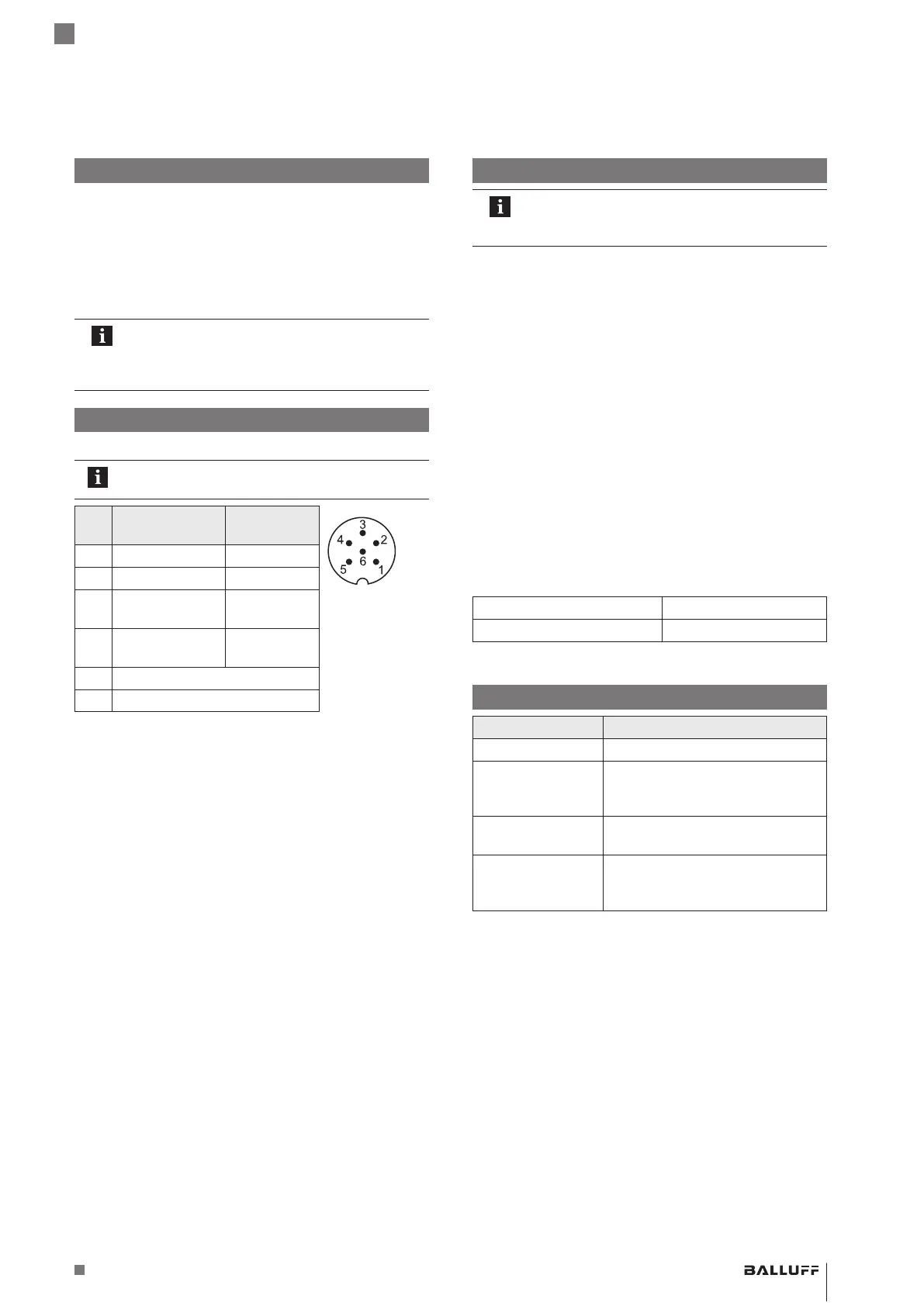
Electrical connection
The electrical connection is made using a connector.
Note the information on shielding and cable
routing.
Pin C15AA/A1… C15AE/A5/
AC5…
Pin assignment
ofS35 (view
from above on
BTL)
1 Output1 Output1
2 0V (output1) 0V
3 Output2 Not
assigned
1)
4 0V (output2) Not
assigned
1)
5 10…30V
6 GND
2)
1)
Unassigned leads that are not used can be connected to the GND on
the controller side but not to the shield.
2)
Reference potential for supply voltage and EMC-GND.
 Loading...


